Electric machine having a rotary and a linear actuator

a technology of linear actuators and electric machines, applied in the field of electric machines, can solve problems such as high feed forces, and achieve the effect of high feed forces

Inactive Publication Date: 2011-09-27
SIEMENS AG
View PDF17 Cites 17 Cited by
  • Summary
  • Abstract
  • Description
  • Claims
  • Application Information

AI Technical Summary

Benefits of technology

[0006]It is the object of the present invention to specify an electric machine of the type mentioned at the beginning with the aid of which it is possible to attain relatively high feed forces by means of the machine part designed as linear actuator.
[0008]With the aid of a secondary part of the second machine part that is designed as an external rotor, it is possible to implement a higher force of a second machine part acting as linear motor, since it becomes possible to enlarge the air gap area of the linear motor without enlarging the external dimensions of the electric machine. This can be achieved by virtue of the fact that it is possible to accommodate in the primary part of the second machine part the electrical windings that produce the main field, whereas permanent magnets for producing the exciting field are accommodated in the secondary part of the second machine part. Since the primary part is provided in the interior of the second machine part, while the secondary part is designed as an external rotor, preferably as a thin hollow cylinder, it is possible to attain larger external dimensions of the primary part such that a larger air gap area can also be provided by means of a larger diameter of the primary part. Owing to such an arrangement, higher magnetic drive forces are produced on the secondary part during operation of the machine such that the force of the linear drive can be increased. A further advantage of the external rotor arrangement resides in the fact that it is technically simpler to apply the electrical windings to the primary part, since the electric conductors can be wound onto the primary part from outside.
[0011]The pin-like or tube-like element is supported with reference to a primary part by means of a plain bearing or a ball bearing, by way of example. In another embodiment, the pin-like or tube-like element is supported with reference to the primary part by means of a cylindrical roller bearing, which is advantageous, in particular, when the aim is to achieve high rotational speeds but only low axial speeds of the electric machine.
[0013]Owing to the restricted installation conditions in a machine tool, for example, and to the high power density of a linear motor, the installation of a cooling device in the primary part of the second machine part is advantageous. In particular, guides are provided for conducting a liquid coolant through, for example for conducting cooling water through, which are arranged in an interior of the primary part. This can easily be achieved by providing in an interior of the primary part longitudinal bores that extend in an axial direction of the primary part in order to export heat axially from the primary part. Such longitudinal bores are advantageously interconnected in meandering fashion at the end faces of the primary part.

Problems solved by technology

The result of this is that known linear motors are capable of implementing high feed forces only to a limited extent, because of a limited linear force.

Method used


Image

  • Electric machine having a rotary and a linear actuator
  • Electric machine having a rotary and a linear actuator

Examples


Embodiment Construction

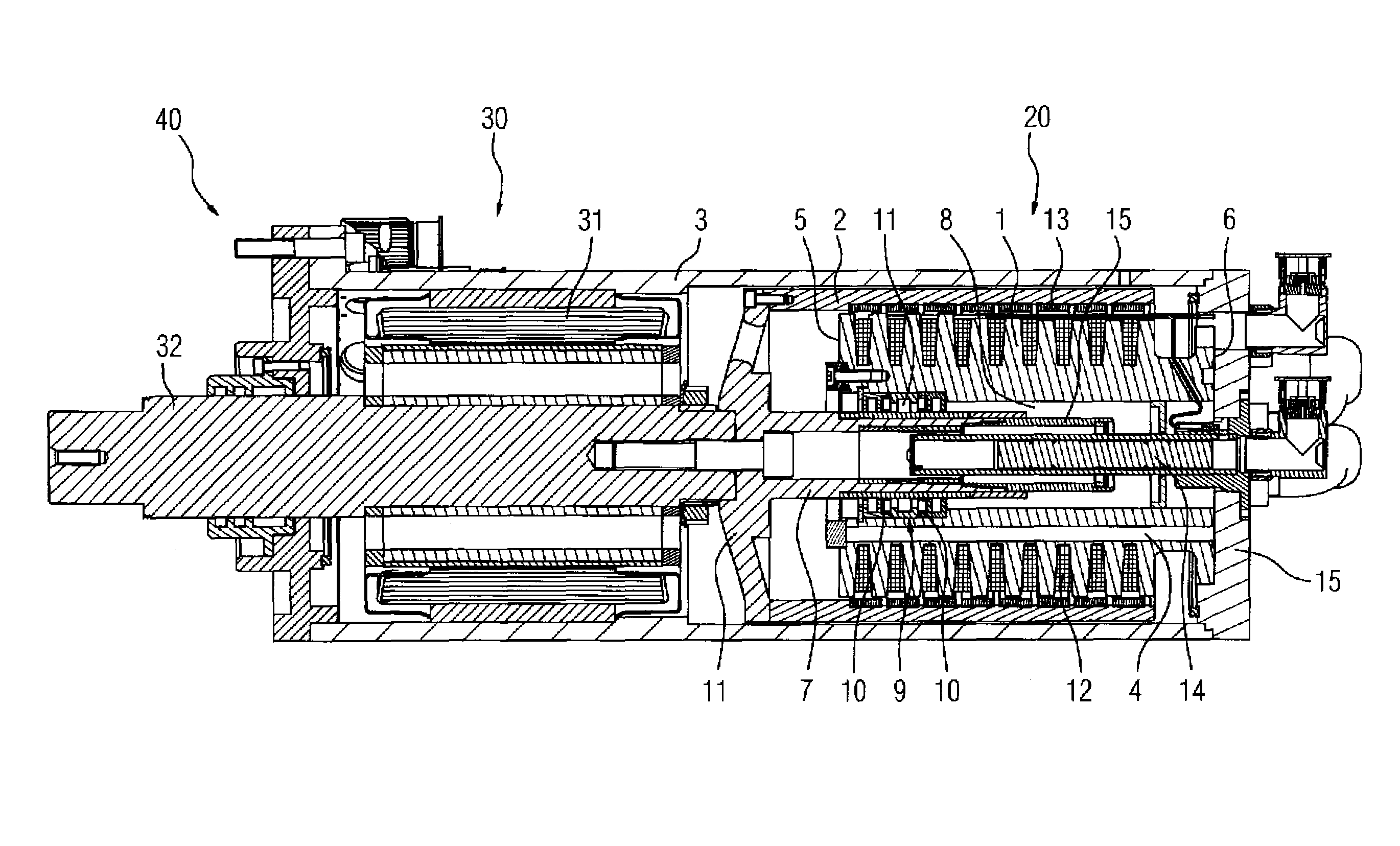
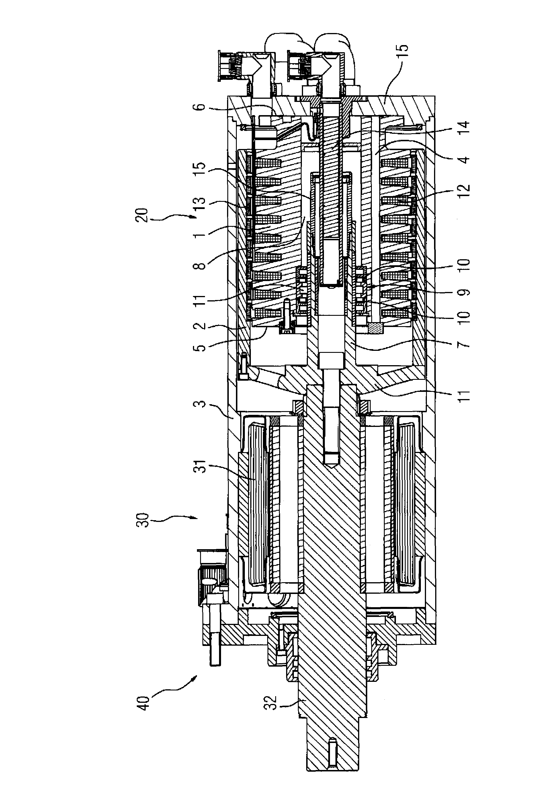
[0018]The FIGURE illustrates an embodiment of an electric machine for implementing a combined rotary and linear drive. The electric machine 40 has a first machine part 30 that has in a stator a stator element 31 with a stator winding (not illustrated in more detail in the FIGURE). The stator of the machine part 30 is designed as a hollow cylinder, there being arranged in the interior of the hollow cylinder a rotor element 32 that is connected to a shaft and can be moved in a rotating fashion. The stator winding of the stator element 31 produces, for example, the main field of the machine part 30, while an exciter winding or alternatively permanent magnets is / are arranged on the rotor element and serve to produce the exciting field. The machine part 30 therefore acts generally as a rotary actuator interacting with a rotary movement of the rotor element 32. In motor mode, the rotor element 32 with the shaft attached thereon is set moving by the stator field, whereas in generator mode,...


PUM


Abstract

The invention relates to an electric machine which comprises a first machine part (30), comprising a stator element (31) and a rotor element (32) and being configured as a rotary actuator which interacts with a rotary movement of the rotor element (32). The electric machine (40) also comprises a second machine part (20), comprising a primary part (1) and a secondary part (2) and being configured as a linear actuator which interacts with a linear movement of the secondary part (2). The rotor element (32) of the first machine part (30) and the secondary part (2) of the second machine part (20) are interlinked. The secondary part (2) of the second machine part (20) can be rotated and is configured as an external rotor. Such a secondary part (2) allows to generate a higher power of a secondary machine part (20) acting as the linear motor. The secondary part (2) is mounted in the center thereof in relation to the primary part (1).

Description

BACKGROUND OF THE INVENTION[0001]The present invention relates to an electric machine having a first machine part, which comprises a rotary actuator, and having a second machine part, which comprises a linear actuator.[0002]Electric machines of the type mentioned at the beginning are used, in particular, as drive devices in machine tools or as roller drive devices, for example in printing machines. Such machines principally require high dynamics, for example when a tool such as a milling machine is to be moved both in a rotary fashion and in a linear one. The aim here is to implement a linear movement in addition to a rotary one, in particular without switching gear and at high feed rates and with high precision.[0003]By way of example, use is made for such an application of electric machines that both have a rotary actuator for converting a rotary driving movement, and have a linear actuator for converting a linear driving movement. Use is made for this purpose of, for example, ele...

Claims


Application Information

Patent Timeline
Patent Type & Authority Patents(United States)
IPC IPC(8): H02K41/02
CPCH02K7/08H02K7/125H02K9/20H02K16/00H02K2201/18H02K9/225
Inventor BOTT, ERICHVOLLMER, ROLFBRAUN, MATTHIASSCHUNK, HOLGER
Owner SIEMENS AG
Why Eureka
Try Eureka