Integrated optic vector-matrix multiplier

Active Publication Date: 2011-09-27
NAT TECH & ENG SOLUTIONS OF SANDIA LLC
View PDF6 Cites 74 Cited by
  • Summary
  • Abstract
  • Description
  • Claims
  • Application Information

AI Technical Summary

Benefits of technology

[0010]The present invention relates to a vector-matrix multiplier for multiplying an N×1 vector and an M×N matrix to generate an M×1 vector-matrix product. The apparatus comprises an optical multiplexer to receive a plurality of N different wavelengths of light corresponding to a number N of rows in the vector and to combine the plurality of N different wavelengths of light into an input wavelength-division-multiplexed (WDM) light stream. Each different wavelength of light (also referred to herein as a channel of light) is modulated with an amplitude which represents a row element ai of the vector with i=1, 2 . . . N. An optical splitter receives the input WDM light stream from the optical multiplexer and splits the input WDM light stream into a plurality of M light streamlets, with each light streamlet being guided out of the optical splitter into a transfer waveguide. A plurality of M×N optical amplitude modulators are further provided in the apparatus and arranged

Problems solved by technology

Vector-matrix multiply operations are highly computationally intensive and are needed for such applications as eigenmode calculations and decoding algorithms.
Traditional digital computers and even vectorizing machines are limited in their ability to perform such computations at high rates of speed.
Despite this seemingly high rate of computation, codes for electromagnetic and quantum systems, for example, often require highly parallel digital computers, which are quite large and power intensive, to run for days at a time to achieve a result.
This is insufficient for many applications which require real time data processing.
Most of these prior art approaches to vector-matrix multiplication are based on free-space optical signal processing approaches which suffer

Method used


Image

  • Integrated optic vector-matrix multiplier
  • Integrated optic vector-matrix multiplier
  • Integrated optic vector-matrix multiplier

Examples


Embodiment Construction

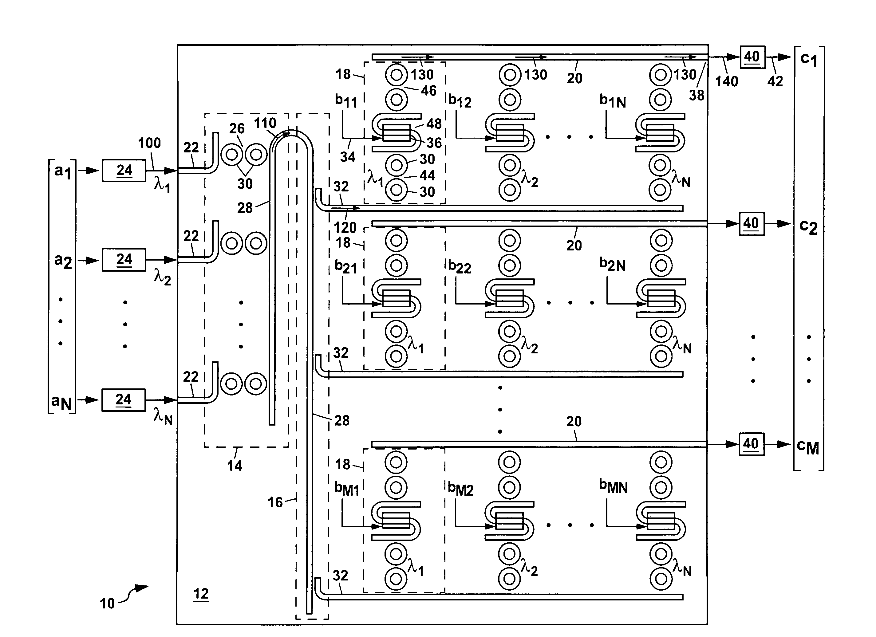
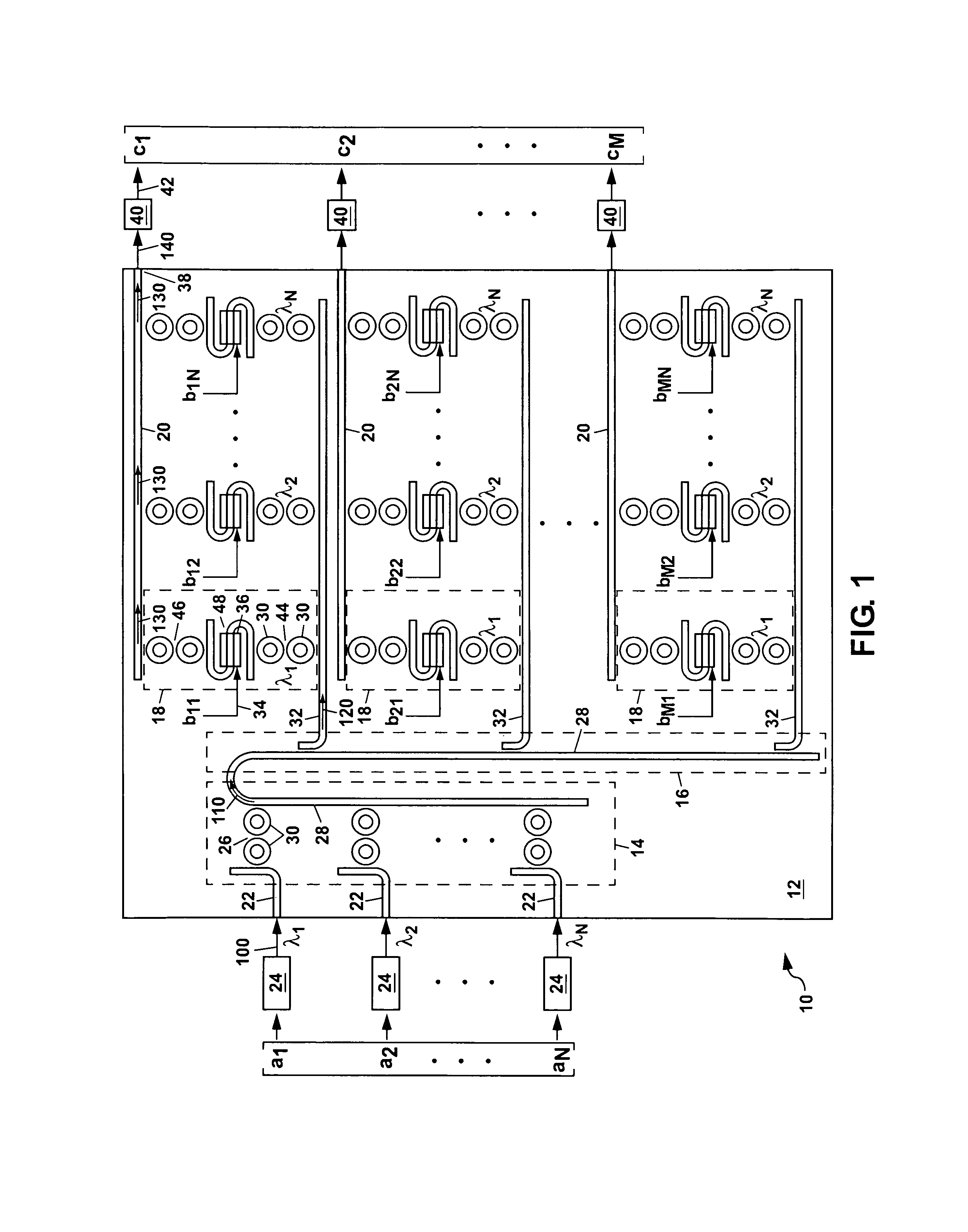
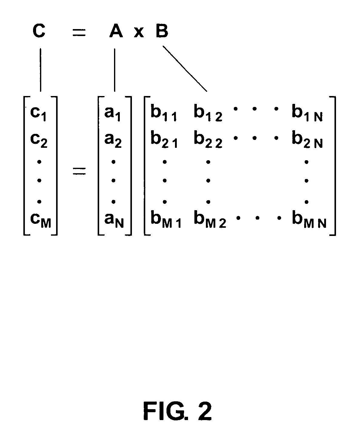
[0035]Referring to FIG. 1, there is shown a schematic plan view of a first example of a vector-matrix multiplier (VMM) 10 according to the present invention. The apparatus 10, which can be formed at least in part as an integrated optic circuit, can be used to multiply an N×1 vector A and an M×N matrix B to generate an M×1 vector-matrix product C. This can be represented mathematically as C=A×B as illustrated in FIG. 2. FIG. 2 also shows in detail the row elements ai with i=1, 2 . . . N for the N×1 vector, the column elements bji with j=1, 2 . . . M and i=1, 2 . . . N for the M×N matrix, and the resulting row elements cj given by:

[0036]cj=∑i=1N⁢⁢ai⁢bji

of the M×1 vector-matrix product C. Those skilled in the art will understand that the rank for the vector A and the matrix B can be arbitrary and can range from as small as one up to hundreds or even thousands or more depending upon the exact vector A and matrix B being multiplied.

[0037]Returning to FIG. 1, the first example of the appa...


PUM


Abstract

A vector-matrix multiplier is disclosed which uses N different wavelengths of light that are modulated with amplitudes representing elements of an N×1 vector and combined to form an input wavelength-division multiplexed (WDM) light stream. The input WDM light stream is split into N streamlets from which each wavelength of the light is individually coupled out and modulated for a second time using an input signal representing elements of an M×N matrix, and is then coupled into an output waveguide for each streamlet to form an output WDM light stream which is detected to generate a product of the vector and matrix. The vector-matrix multiplier can be formed as an integrated optical circuit using either waveguide amplitude modulators or ring resonator amplitude modulators.

Description

CROSS REFERENCE TO RELATED APPLICATIONS[0001]The present application hereby claims the benefit of previously filed U.S. provisional patent application Ser. No. 60 / 956,968, entitled “Integrated Optic Vector-Matrix Multiplier,” filed on Aug. 21, 2007, the contents of which are incorporated herein by reference in their entirety.[0002]The present application is also related to U.S. patent application Ser. No. 12 / 100,004, entitled “Wavelength Tunable Optical Ring Resonators,” of common assignee filed on Apr. 9, 2008, the contents of which are incorporated herein by reference in their entirety.GOVERNMENT RIGHTS[0003]This invention was made with Government support under Contract No. DE-AC04-94AL85000 awarded by the U.S. Department of Energy. The Government has certain rights in the invention.FIELD OF THE INVENTION[0004]The present invention relates in general to integrated optical circuits (also termed photonic integrated circuits), and in particular to integrated optical circuits which ca...

Claims


Application Information

Patent Timeline
IPC IPC(8): H04J14/02
CPCG02B6/12007G02B6/29343G02F1/025G02F1/2257G02F2203/055G02F2203/15G02F2203/58G02F3/00G06E1/045
Inventor WATTS, MICHAEL R.
Owner NAT TECH & ENG SOLUTIONS OF SANDIA LLC
Why Eureka
Try Eureka