2D/3D switchable color display apparatus with narrow band emitters

a color display and switchable technology, applied in the field of display devices, can solve the problems of no commercially available 3d display for use in the home, dedicated 3d display, complex approaches, etc., and achieve the effect of enhanced color gamut and high color gamu

Inactive Publication Date: 2011-10-04
EASTMAN KODAK CO
View PDF19 Cites 165 Cited by
  • Summary
  • Abstract
  • Description
  • Claims
  • Application Information

AI Technical Summary

Benefits of technology

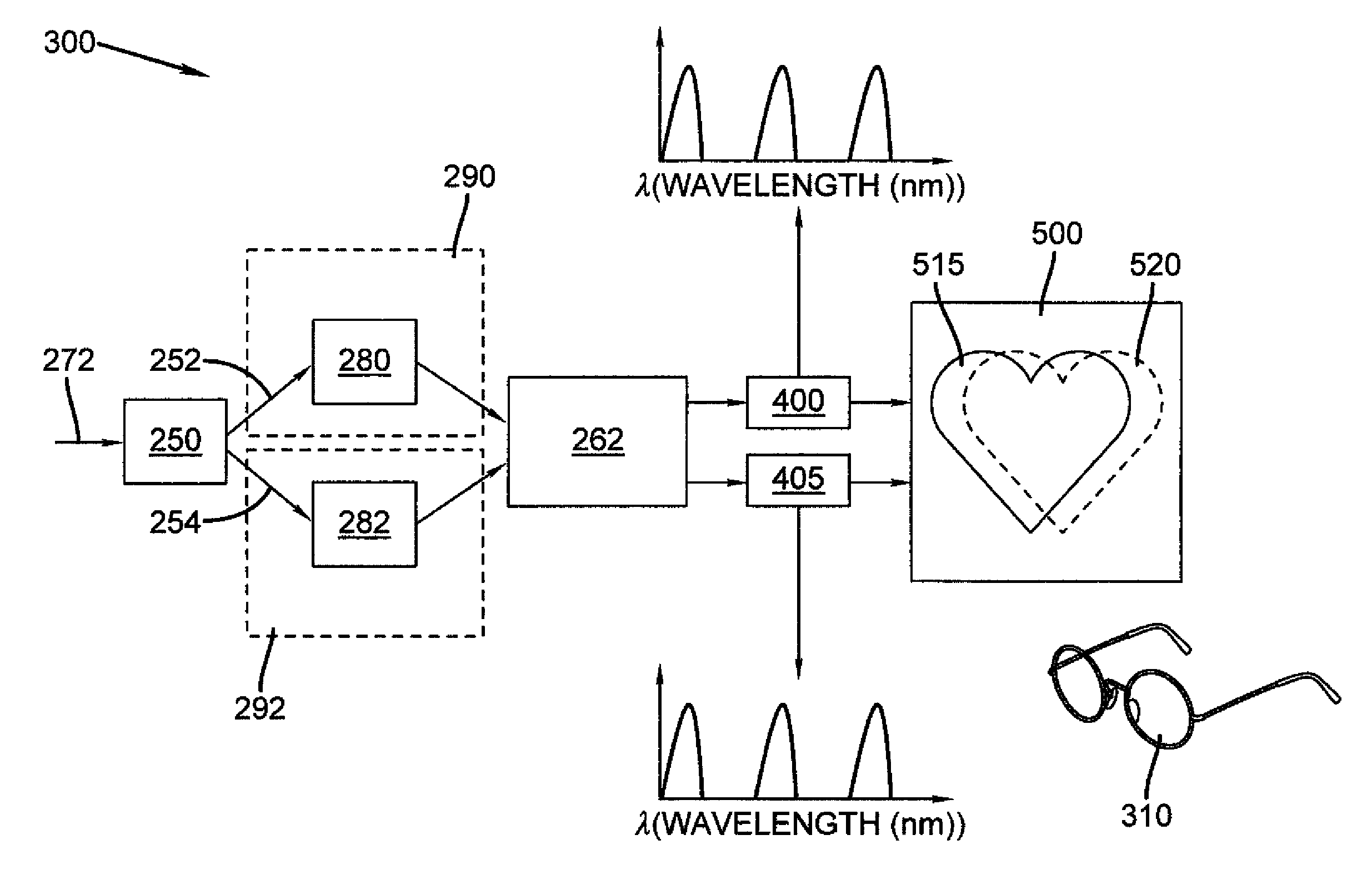
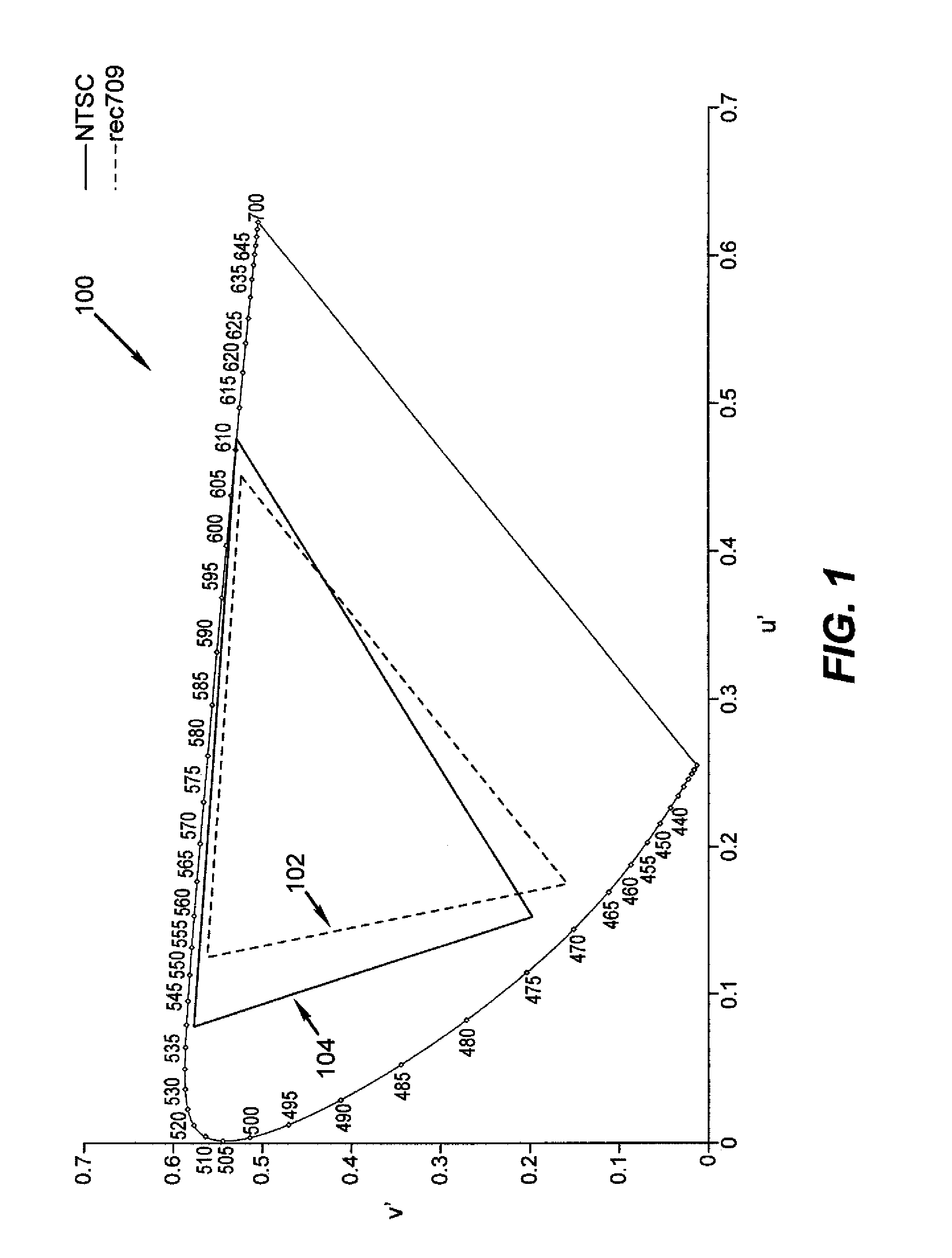
[0023]It is an advantage of the present invention that it provides an apparatus capable of displaying high color gamut 3D images, and of achieving enhanced color gamut for displaying 2D digital images when compared against conventional 3-color display equipment such as color monitors. The apparatus and method of the present invention allows the 2D display of colors that were not achievable with 3-color systems, and enables a 2D / 3D switchable display for home use.

Problems solved by technology

To-date, there is no commercially available 3D display for use in the home.
Since the amount of 3D content is currently limited, there is not a large market at the present for a dedicated 3D display for home use.
Unfortunately, these approaches are complex and expensive to manufacture, and the image quality is poor in 3D viewing mode, due to well-known difficulties in the angular dependence of the light modulation mechanisms in such technologies.
Further, these technologies require the movement or alteration of physical structures inside the device to switch between 2D and 3D viewing modes.
However, the electronics for driving a 3D display using shutter glasses are complex.
Anaglyph has a significant amount of color-cross talk and has many objectionable image artifacts.
Projection systems use a special polarization preserving screen, which considerably raises the complexity and cost of such devices.
Much like the polarization method, the luminance of these systems is low due to the inefficient use of the projector light by the filters.
It has been proposed that the Infitec system would work best as a projection systems using laser sources, however, this is not known to have been actually implemented in practice.
Additionally, with the exception of the Infitec system, all of the 3D technologies above use only broadband light sources, and are not designed for sources with narrow emission spectra.
For the Infitec system, filtering of a broadband source to create two sets of primaries does not impart any benefit for 2D operation over that of a conventional display.
Placing the corresponding primaries near each other needlessly limits the 2D performance in a 2D / 3D switchable display system.
Generally these systems are not suitable for 3D display by wavelength segregation since the position of the emitters would not allow for the division of these six or more emitters into filterable groups of emitters.
However, the bulk of solutions proposed have not targeted color gamut expansion.
Although such an approach may be useful to enhance brightness and luminance for some colors, the addition of complementary CMY colors does not expand the color gamut and, in practice, could result in a smaller color gamut, as indicated in the disclosure of U.S. Pat. No. 6,280,034.
Additionally, the embodiment disclosed in U.S. Pat. No. 6,280,034 uses light sources having different polarizations, which prevents use of an analyzer for improving contrast.
However, the embodiments disclosed in U.S. Pat. No. 6,769,772 teach against using two different red emitters, and therefore would not be suitable for use in 3D applications using spectral selection.
Moreover, the use of a filter wheel for providing the successive component colors at a sufficiently high rate of speed has further disadvantages.
The additional “dead time” during filter color transitions, already substantial in devices using 3-color filter wheels, further reduces brightness and complicates timing synchronization.
Coupling the filter wheel with a neutral density filter, also rotating in the light path, introduces additional cost and complexity.
Although rotating filter wheels have been adapted for color projection apparatus, the inherent disadvantages of such a mechanical solution are widely acknowledged.
Further, without some shuttering means, color crosstalk becomes a problem.
Providing illumination from a single light source results in reduced brightness and contrast.
Moreover, the added cost in using four or more spatial light modulators may not justify an incremental improvement in color gamut for consumer projection devices.
Thus, while the disclosure of application WO 01 / 95544 teaches gamut expansion in theory, in practice there are a number of significant drawbacks to the design solutions proposed.
As a studied consideration of application WO 01 / 95544 clearly shows, problems that were difficult to solve for 3-color projection, such as timing synchronization, color alignment, maintaining brightness and contrast, cost of spatial light modulators and overall complexity, are even more challenging when attempting to use four or more component colors.
Lamps and other broadband light sources set practical limits on achievable brightness levels, particularly where color filter wheels or similar devices that cause some amount of light attenuation or have inherent “dead space” during transitions are employed.
The use of color wheels makes it unwieldy to alter or adjust illumination timing.
The design of practical 2D / 3D switchable displays for home use has not been completely addressed.
Additionally, the tradeoff between performance in 2D mode and 3D mode for color gamut and luminance efficiency has not been completely addressed.

Method used


Image

  • 2D/3D switchable color display apparatus with narrow band emitters
  • 2D/3D switchable color display apparatus with narrow band emitters
  • 2D/3D switchable color display apparatus with narrow band emitters

Examples


Embodiment Construction

[0044]The present description is directed in particular to elements forming part of, or cooperating more directly with, apparatus in accordance with the invention. It is to be understood that elements not specifically shown or described may take various forms well known to those skilled in the art.

[0045]As discussed above, there is a need to have a low cost 2D / 3D switchable display for consumer use to expand the potential market for 3D content. In order to achieve this goal, it is important to have a high efficiency system, leading to a lower power display. There are many types of display technology that can be used to create the display system of the present invention, however, all of the inventive systems utilize narrow band emitters that define six primaries of the 2D display. Preferably, the emitters are not filtered in 2D display mode. Examples of potentially useful display technologies for 2D / 3D switchable displays include rear and front projection displays with either spatial...


PUM


Abstract

A 2D / 3D switchable display system having a selector for selecting a two-dimensional (2D) or a three-dimensional (3D) image processing path; a first processor for processing image data through the two-dimensional image processing path; a second processor, independent of the first processor, for processing image data through the three dimensional image processing path; a first set of at least three emitters having corresponding first wavelengths; a second set of at least three emitters having corresponding second wavelengths; and a controller that during a 2D operation activates both first and second sets of emitters to present a single image, while during a 3D operation activates the first set of emitters to present a first image having one half of stereo image information and activates the second set of emitters to present a second image having a second half of stereo image information.

Description

FIELD OF THE INVENTION[0001]This invention generally relates to a display apparatus for forming color images from digital data that can be operated in either standard two dimensional (2D) mode, or in three dimensional (3D) mode.BACKGROUND OF THE INVENTION[0002]There are a number of technologies existing today for displaying 3D images to multiple viewers. Generally, these technologies are implemented in locations where a large number of viewers will pass through, and often pay for the 3D experience. These locations include movie theatres, science centers and the like. To-date, there is no commercially available 3D display for use in the home. Since the amount of 3D content is currently limited, there is not a large market at the present for a dedicated 3D display for home use. To open up the 3D market for home entertainment, a 2D / 3D switchable display is needed.[0003]The available technologies for displaying 3D images include 3D model rendering, stereoscopic, volumetric and holograph...

Claims


Application Information

Patent Timeline
Patent Type & Authority Patents(United States)
IPC IPC(8): G03B21/00H04N13/363
CPCG02B27/2207H04N13/0422H04N13/0431H04N13/0454H04N13/0459H04N13/324H04N13/334H04N13/363H04N13/359G02B30/23
Inventor ELLINGER, CAROLYN R.KANE, PAUL J.
Owner EASTMAN KODAK CO
Why Eureka
Try Eureka