
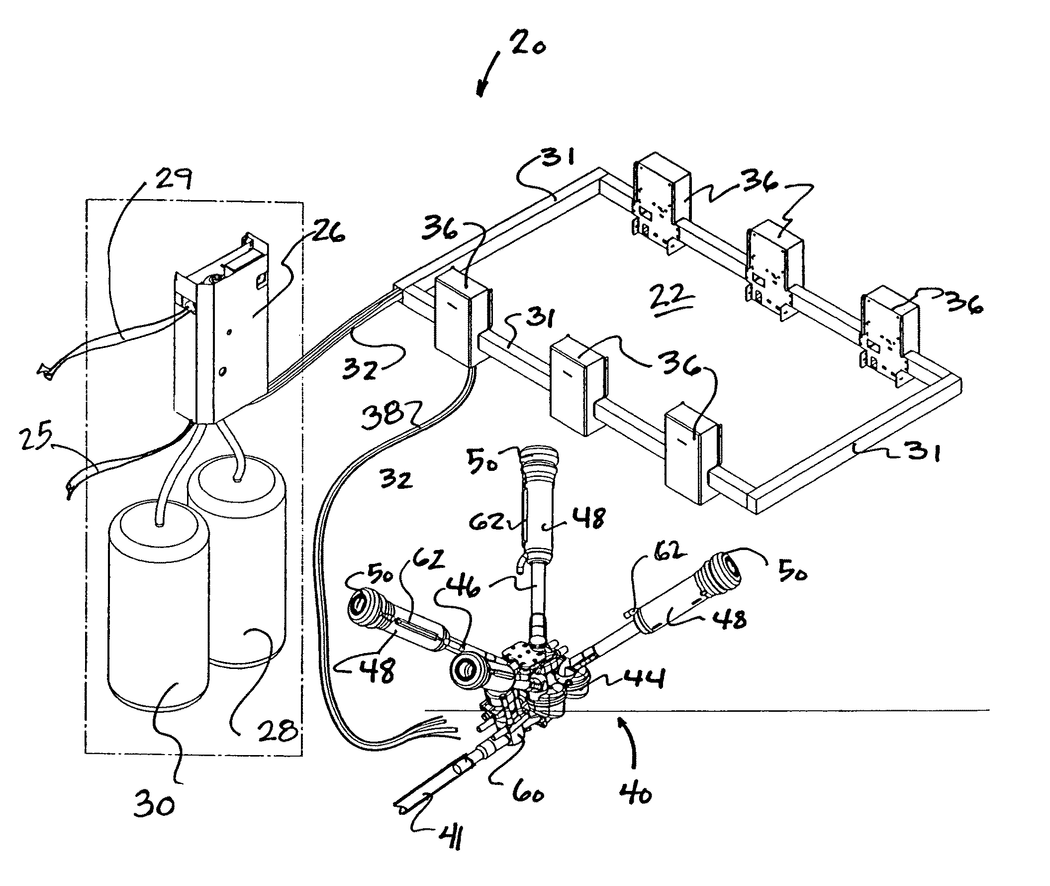
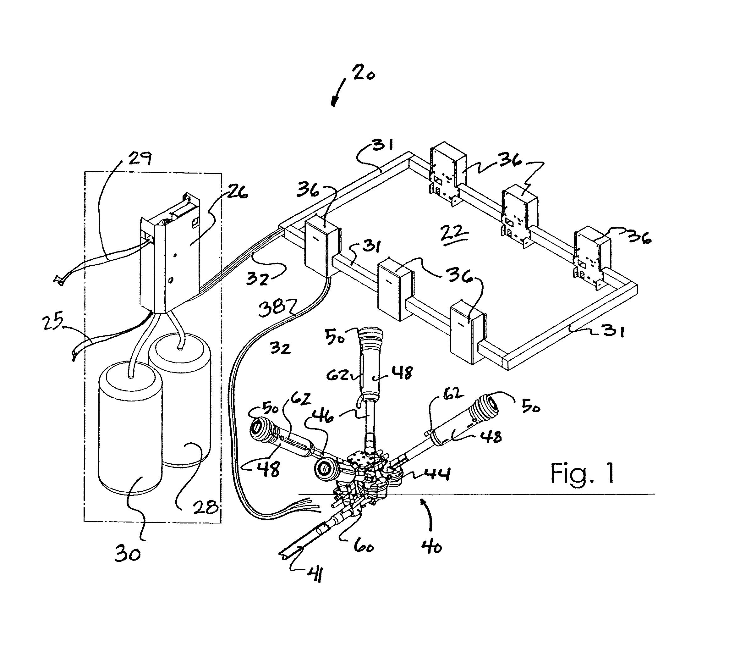
Automatic dairy animal milker unit backflusher and teat dip applicator system and method

a technology of backflushing system and milker unit, which is applied in the direction of milking device, thin material processing, cleaning using liquids, etc., can solve the problems of inconvenient use, high water consumption and cleaning chemicals, and inability to accurately and precisely spray the automatic sprayer, so as to reduce the number of operators and reduce the number of pathogenic organisms , the effect of reducing operator fatigu

Active Publication Date: 2011-10-11
GEA FARM TECH
View PDF137 Cites 59 Cited by
  • Summary
  • Abstract
  • Description
  • Claims
  • Application Information

AI Technical Summary

Benefits of technology

The system effectively reduces operator effort, ensures consistent and uniform teat dip application, minimizes chemical and water consumption, and prevents contamination of the dairy milk lines, improving udder health and hygiene.

Problems solved by technology

This latter method involves very high consumption of water and cleaning chemicals, and can waste milk that is in the long milk tube that is otherwise salable.
In addition, dairy animal teats have broadened milk ducts after milking that make them especially susceptible to new infection from mastitis pathogens.
Automated sprayers are not precise and tend to consume much more dipping solution than manual dipping methods.
Others have suggested automated systems that apply dip to an upper teat portion, but most of these failed to provide: uniform dip coverage on teats; consistent volumes of dip application over time; and protection of downstream milk system components from being contaminated by dip and other chemicals.
In particular, most prior automatic teat dip applicators and milker unit cleaner systems fail to adequately ensure that teat dip compositions and backflushing fluids do not enter the long milk tube and contaminate the dairy milk lines.
This problem can be caused by a number of factors, but one possible cause for contamination results from differential pressures that develop in dipping and backflushing devices that are connected to milk lines.
Differential pressures between the milk lines, and dipping and backflushing devices can cause seepage even through closed valves and tight seals, so it is difficult to design, build, install, maintain, and use automated teat dip applicators and milker unit backflushing systems that are safe and prevent contamination of dairy systems.

Method used


Image

  • Automatic dairy animal milker unit backflusher and teat dip applicator system and method
  • Automatic dairy animal milker unit backflusher and teat dip applicator system and method
  • Automatic dairy animal milker unit backflusher and teat dip applicator system and method

Examples


second embodiment

a backflush operation plate 230 is illustrated in FIGS. 9A, 9B, 12C and 12D, and has a central opening 231 and a recess 238 for receiving the lip 239 of the backflush piston 120. Reinforcing ribs 233 are formed above and below a wall 232.

This embodiment of the backflush operation plate 230 includes integrally molded seals 235 and 237 around the outer annular surface and an integrally molded seal 239 and 241 around the inner annular surface. This design is less costly, requires fewer parts, and is easier to assemble and replace.

The upper seals 235 and 239 seal air pressure to move the backflush piston 120 into a backflush position. The lower seals 237 and 241 wipe dirt and debris from mating surfaces when moving to the backflushing position, and seal out water during a self-cleaning cycle.

Extending though the central opening 231 of the backflush operation plate 230, is a central shaft 198 of the upper housing 74 (described in detail below). Extending through the central shaft 162, is...


PUM


Abstract

A system for cleaning a dairy animal milker unit and applying dip to a dairy animal, the system includes a main control, an air supply, a water supply, a backflush fluid supply, a dip supply, a stall control for receiving the air, water, backflush fluid and dip supplies, and a safety valve that is adjacent to a downstream portion of the milker unit to control backflush and dip fluids being fed to the milker unit.

Description

FIELD AND BACKGROUND OF THE INVENTIONThis invention relates generally to teat dip applicators and backflushing systems for dairy animal milker units, and more particularly to automatic milker unit backflushing systems, teat dip applicators, related components, and methods for safely and efficiently applying dips and backflushing milker units.Dairy milking systems as they relate to the present invention include a cluster of teat cups, each of which is matched with a flexible teat cup liner that is attached to a teat of a dairy animal with a vacuum. Vacuum is applied in pulses between the shell and liner to facilitate movement of the flexible liner to milk the dairy animals. Milk flows from the cow through each flexible liner and then through a short milk tube to a milker unit collecting bowl assembly, which collects milk from all of the animal's teats. This combination of elements is known as a milker unit and can be used to milk cows, sheep, goats and other dairy animals. Each milke...

Claims


Application Information

Patent Timeline
Patent Type & Authority Patents(United States)
IPC IPC(8): A01J7/02
CPCA01J7/04A01J5/047A01J7/00A01J7/02A01J7/022A01J7/025Y10T137/2546Y10T137/4245Y10T137/4252Y10T137/8593Y10T137/87684
Inventor TORGERSON, KEVIN L.HEDLUND, NATHANSTUESSEL, MATTHEW J.
Owner GEA FARM TECH
Learn More