Method for determining fatigue load of a wind turbine and for fatigue load control, and wind turbines therefor

a technology of wind turbines and fatigue loads, which is applied in the direction of wind energy generation, liquid fuel engine components, special data processing applications, etc., can solve the problems of wind turbine fatigue damage, wind turbines that do not produce energy, and unusable times of unavailability, so as to reduce the amount of sensors, reduce the complexity of calculation, and increase the robustness of the sensor system

Inactive Publication Date: 2011-10-11
SIEMENS GAMESA RENEWABLE ENERGY AS
View PDF11 Cites 21 Cited by
  • Summary
  • Abstract
  • Description
  • Claims
  • Application Information

AI Technical Summary

Benefits of technology

[0015]It is thus an object of the present invention to provide a method for determining fatigue loads of a wind turbine that reduces the amount of sensors that are required while increasing the robustness of the sensor systems, and, at the same time, reduces calculation complexity as compared to the discussed systems of the state of the art.
[0021]In the inventive method, the transfer function allows for correctly associating the obtained measurement values of the first sensor to the obtained measurement values of the second sensor. It thus enables to feed further measurement values derived from the first sensors, or equivalent sensors, into the transfer function and obtain function values that correspond to measurement values that would have been measured at the second sensors. It is thus possible to calculate, or at least approximate, values corresponding to the second sensors with the help of the transfer function and the actually measured values from the first or equivalent sensors instead of actually performing measurements at the second set of sensors once the transfer function is established.
[0023]As opposed to the reference wind turbine, the operative wind turbines only comprise a reduced total amount of sensors as compared to the reference wind turbine, namely only a third sensor or a set of third sensors that correspond to the first sensor or set of sensors of the reference wind turbine, preferably in number, type, and position. Measurement values at the operative wind turbine are thus obtained by said third sensor or set of sensors. Hence, the technical cost and complexity of a full sensor equipment is centralized at one or only a small number of reference wind turbines, while a comparatively large number of operative wind turbines benefit from a reduced number and complexity of sensors.
[0025]Thus, the present method enables to reduce the sensors used at the operative wind turbine (third set of sensors) to a minimum in number and in sensor complexity. As a result, it is moreover easy to establish redundancy with backup instruments to ensure that the monitoring system is always operational. Also, with such a form of transfer function, the fatigue load can be calculated based on the transfer function values by immediately taking over the transfer function values without further advanced data analysis. In more detailed embodiments, such as described below or in the detailed example, additional signal processing may be performed. Since the transfer function values can be calculated in a rather straightforward manner on the basis of the established transfer function, calculation complexity is reduced.
[0033]While this method of controlling a wind turbine shares the desirable technical effects of reliable fatigue load calculation with a reduced amount of technical effort for sensor equipment and calculation, it further allows to control wind turbine behaviour with respect to the fatigue load that occurs, or has occurred so far, for the wind turbine. By using this method of wind turbine control, safety redundancies in the design of the wind turbine structural elements can be further reduced while continuing to meet the required safety properties.

Problems solved by technology

However, shutting down a wind turbine in such a manner produces undesired times of unavailability, in which the wind turbine does not produce energy.
Further, the shutdown process may by itself add to the overall fatigue damage of the wind turbine.
However, the use of strain gauges for directly measuring the mechanical loads acting on the wind turbine suffer from the disadvantage that strain gauges, such as bonded or welded strain gauges, require expertise to install and maintain and moreover have only a comparatively short technical lifespan.
However, this method has the disadvantage that shaft deflections may be caused by numerous factors, including internal bearing play and flexibility.
However, the wind speed measurement is taken at a certain point, such as at hub height, so that the point at which the measurement is taken is not indicative of the wind speed that actually acts at the rotor disk.
These methods however do not take into account accumulated fatigue data and will therefore perform more load regulation over the lifetime of the wind turbine than may be needed when talking into account “unused” fatigue capacity.

Method used


Image

  • Method for determining fatigue load of a wind turbine and for fatigue load control, and wind turbines therefor
  • Method for determining fatigue load of a wind turbine and for fatigue load control, and wind turbines therefor
  • Method for determining fatigue load of a wind turbine and for fatigue load control, and wind turbines therefor

Examples


Embodiment Construction

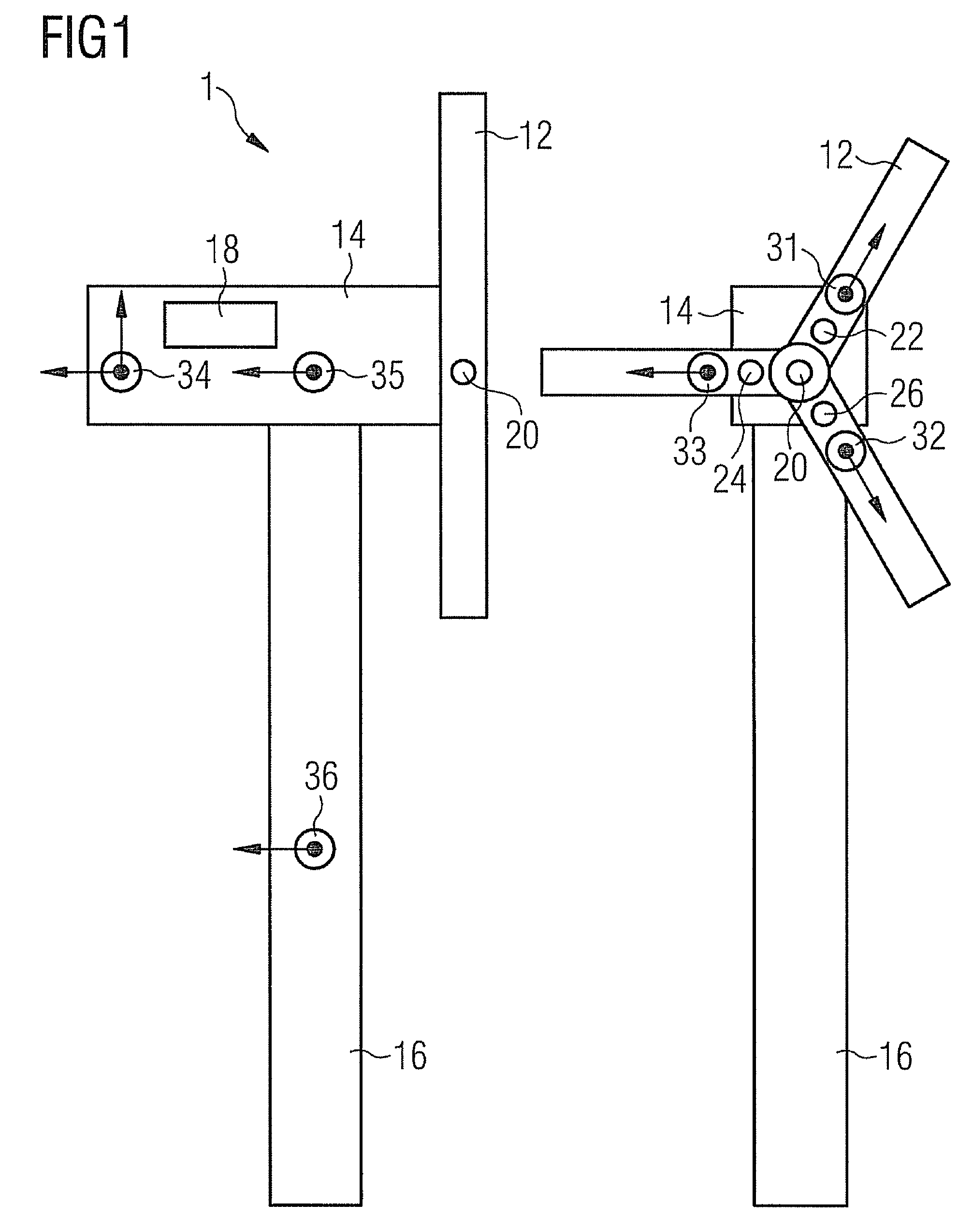
[0060]FIG. 1 shows a schematic overview of an embodiment of the reference wind turbine. Reference wind turbine 1 is depicted in a side view on the left hand side of FIG. 1, and in a front view on the right hand side of FIG. 1. Reference wind turbine 1 comprises a rotor 12, a nacelle 14, a processing unit 18, and a wind turbine tower 16.

[0061]The rotor 12 is connected to nacelle 14 via a rotor hub (not shown) at the centre or rotor rotational axis of rotor 12 and the extension of the rotational axis in the nacelle 14. The nacelle 14 is mounted on top of the wind turbine tower 16.

[0062]In the present embodiment, processing unit 18 is located in the nacelle and is connected to various sensors and / or other devices throughout the wind turbine, as will be described in more detail below. Processing unit 18 may also be located in other parts of the wind turbine or in a separate processing device that may be connected with the wind turbine via a communication line.

[0063]A first set of sensor...


PUM

PropertyMeasurementUnit
frequenciesaaaaaaaaaa
frequency analysisaaaaaaaaaa
frequencyaaaaaaaaaa

Abstract

A method of determining fatigue load of at least one operative wind turbine, comprising: providing a transfer function that associates an obtained at least one measurement value of a first sensor to an obtained at least one measurement value of a second sensor the at least one measurement value of the first sensor and the at least one measurement value of the second sensor being obtained by use of a reference wind turbine at which the first sensor and the second sensor are located; obtaining at least one measurement value of a third sensor, wherein the third sensor is located at the at least one operative wind turbine, and wherein the third sensor corresponds in type and position to the first sensor at the reference wind turbine; calculating at least one transfer function value corresponding to the obtained at least one measurement value of the third sensor by use of the provided transfer function; calculating the fatigue load of the at least one operative wind turbine based on the calculated transfer function value.

Description

CROSS REFERENCE TO RELATED APPLICATIONS[0001]This application claims the benefits of Provisional application No. 61 / 020,209 filed Jan. 10, 2008 and is incorporated by reference herein in its entirety.FIELD OF INVENTION[0002]This invention relates to a method of determining fatigue load of a wind turbine, and a method of controlling a wind turbine, a wind turbine, and a reference wind turbine therefor.BACKGROUND OF THE INVENTION[0003]In order to reduce technical effort in wind turbine manufacturing, it is desired to reduce safety redundancies in the design of wind turbine supporting structures.[0004]Limits for reducing such safety redundancies are usually defined by the mechanical stress that affects the wind turbine. A known approach is thus to design the wind turbine structures so as just to withstand the cumulative fatigue loading on the structure throughout its design life when operating under a given set of environmental conditions.[0005]Wind turbines are often operated under co...

Claims


Application Information

Patent Timeline
Patent Type & Authority Patents(United States)
IPC IPC(8): B63H3/00G01L3/00B64C11/00B64C27/00F03B7/00G01L1/00G01L5/00
CPCF03D7/0292F03D7/042F03D11/0091F05B2270/332F05B2270/334F05B2270/80F05B2270/807F05B2270/808Y02E10/723Y02E10/722F03D17/00Y02E10/72
Inventor EGEDAL, PERSTIESDAL, HENRIK
Owner SIEMENS GAMESA RENEWABLE ENERGY AS
Why Eureka
Try Eureka