Immersion exposure apparatus and device manufacturing method
a technology of immersion exposure and manufacturing method, which is applied in the direction of photomechanical treatment, printing, instruments, etc., can solve the problems of droplet contamination, aberration in the projection optical system, and droplet remains, so as to reduce the amount of droplet remaining
- Summary
- Abstract
- Description
- Claims
- Application Information
AI Technical Summary
Benefits of technology
Problems solved by technology
Method used
Image
Examples
first exemplary embodiment
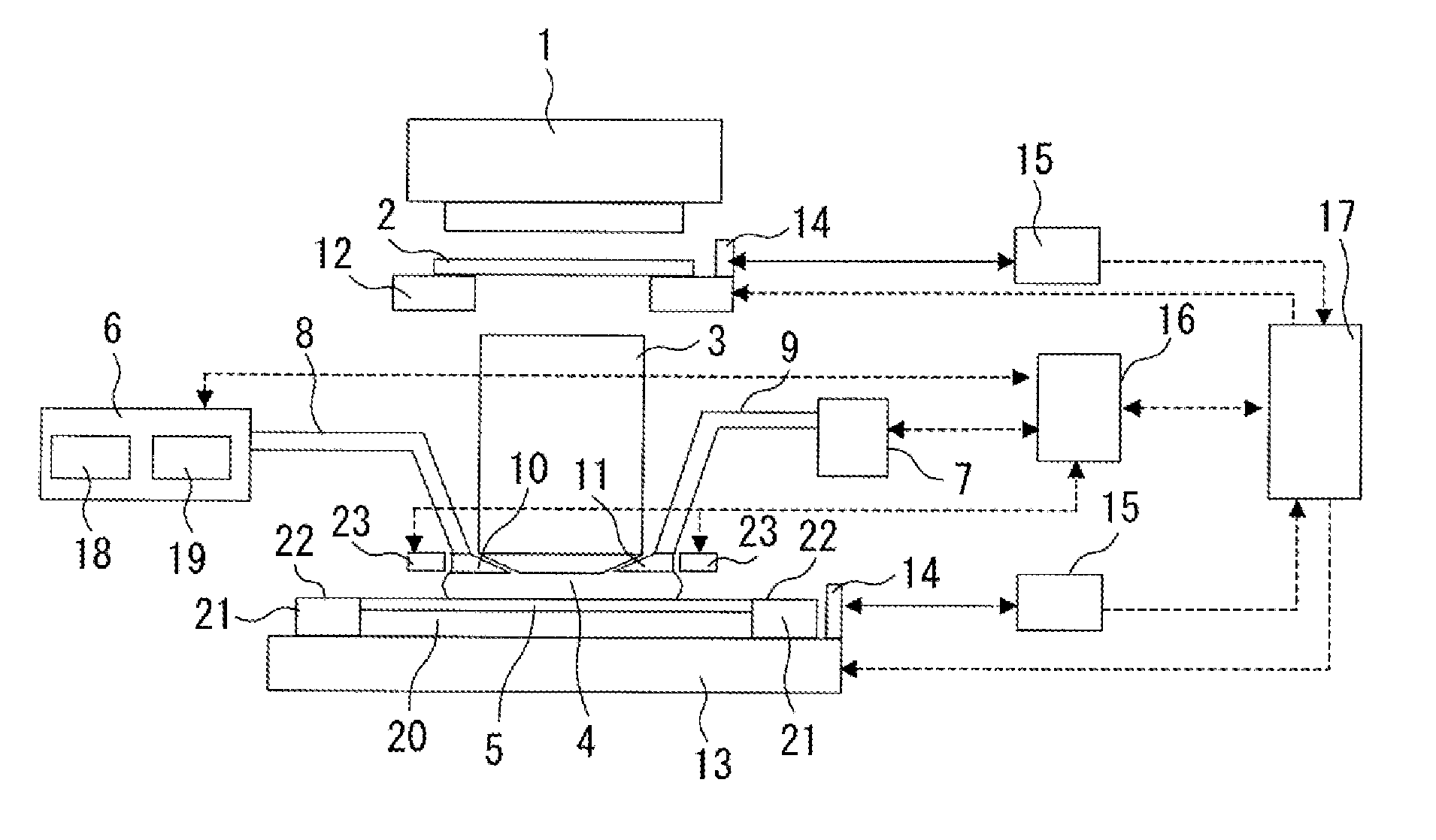
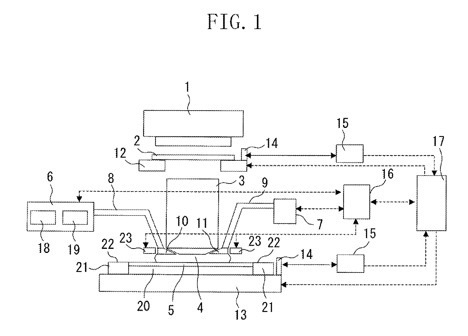
[0034]FIG. 1 illustrates an example configuration of an immersion exposure apparatus according to a first exemplary embodiment of the present invention. According to the first exemplary embodiment, the present invention is applied to a scanning type immersion exposure apparatus.
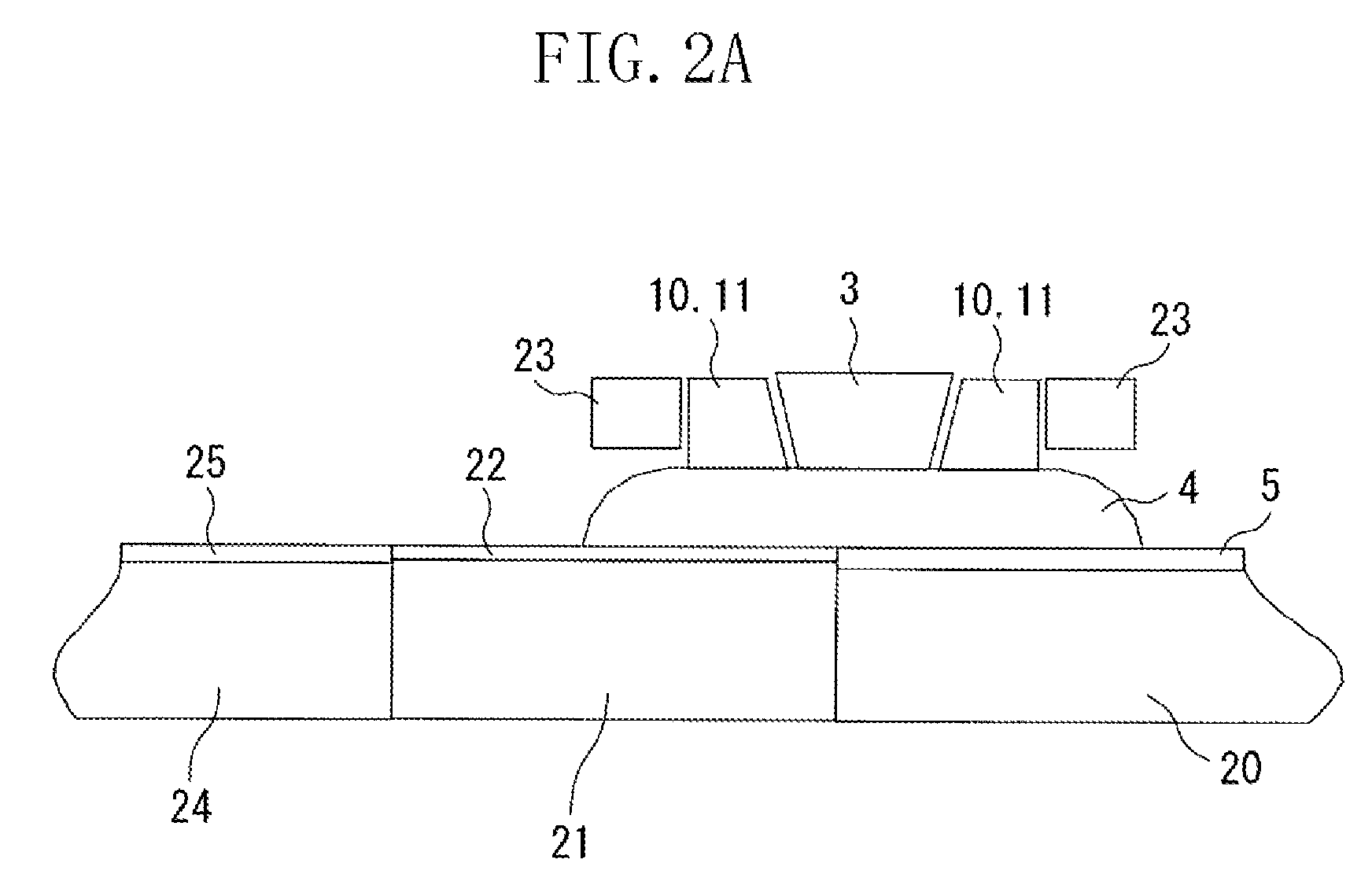
[0035]In FIG. 1, an illumination apparatus 1 irradiates a reticle (mask) 2 serving as an original with exposure light. The illumination apparatus 1 includes an ArF excimer laser (wavelength of 193 nm) as an exposure light source and an illumination optical system. A projection optical system 3, which is a refractive type or a catadioptric type, projects a circuit pattern of the reticle 2 irradiated by the illumination apparatus 1 onto a wafer 5 that is a substrate to be exposed. A laser interferometer 15 for measuring a distance measures a two-dimensional position of a reticle stage 12 or a wafer stage 13 within a level plane through a reference mirror 14. Based on the thus measured value, a stage control dev...
second exemplary embodiment
[0043]FIG. 3 illustrates a vicinity of the liquid film 4 and a part about a half from a center of the projection optical system 3 of the immersion exposure apparatus according to a second exemplary embodiment of the present invention. In the second exemplary embodiment, there are two light sources 23 at both sides of the supply port 10 and the collecting port 11. With such an arrangement, more light can fall onto the surface of the metal oxide 22 and thus the water repellency of the metal oxide 22 can be more favorably maintained and recovered. The two irradiating light sources 23 may have a different wavelength. The optimum wavelengths may be chosen according to a combination with the metal oxide.
[0044]The second exemplary embodiment is identical to the first exemplary embodiment except that the projection optical system 3 includes two light sources 23 for allowing the surface of the metal oxide on the liquid support plate 21 to maintain or recover a function of the water repellenc...
third exemplary embodiment
[0045]FIG. 4 illustrates a vicinity of a liquid film 4 and apart about a half from a center of the projection optical system 3 of the immersion exposure apparatus according to a third exemplary embodiment of the present invention. The third exemplary embodiment includes light sources 23 as a liquid repellency recovery unit below the liquid support plate 21 (at the wafer stage 13 side) . The liquid support plate 21 is made of a transparent base material which transmits the irradiating light emitted from the light sources 23, and the light sources 23 irradiate a reverse side of the light support plate 21 with the irradiating light. The irradiated light that is emitted from the light sources 23 and passes through the transparent base material falls further onto the metal oxide 22. Here, it is desirable that the film thickness of the metal oxide is equal to or less than 100 nm. Further, the material of the liquid support plate 21 may be any material hardly susceptible to deterioration b...
PUM
 Abstract
Description
Claims
Application Information
 - R&D
- Intellectual Property
- Life Sciences
- Materials
- Tech Scout
- Unparalleled Data Quality
- Higher Quality Content
- 60% Fewer Hallucinations
Browse by: Latest US Patents, China's latest patents, Technical Efficacy Thesaurus, Application Domain, Technology Topic, Popular Technical Reports.
© 2025 PatSnap. All rights reserved.Legal|Privacy policy|Modern Slavery Act Transparency Statement|Sitemap|About US| Contact US: help@patsnap.com


