Light source unit and object reader

a technology of object reader and light source unit, which is applied in the field of light source unit, can solve the problems of large amount of light, displacement of irradiated position, and error in the accuracy of the attachment of the optical moving part (carriage) and the displacement of the irradiated position,

Inactive Publication Date: 2011-10-11
STANLEY ELECTRIC CO LTD
View PDF5 Cites 9 Cited by
  • Summary
  • Abstract
  • Description
  • Claims
  • Application Information

AI Technical Summary

Benefits of technology

[0026]As a result, the light source can be configured to have a smaller loss in light guided through the lens, a higher utilization of light, and a larger amount of light applied to the document surface.
[0029]The optimization of the shape of the rod lens can be realized through a low-cost method and provide certain advantages and improvements.

Problems solved by technology

In this case, an error in accuracy of attachment of the optical moving part (carriage) and a displacement of the irradiated position due to vibrations when moving (scanning) may occur.
The wide-directivity light source provides a large amount of light that can not contribute to reading the document image 54 ( i.e., there is an inherent loss in light) and the light from the light source can not be utilized sufficiently.
However, the use of two halogen lamps in the light source increases the material expense and size and causes an increase in production costs.

Method used


Image

  • Light source unit and object reader
  • Light source unit and object reader
  • Light source unit and object reader

Examples


Embodiment Construction

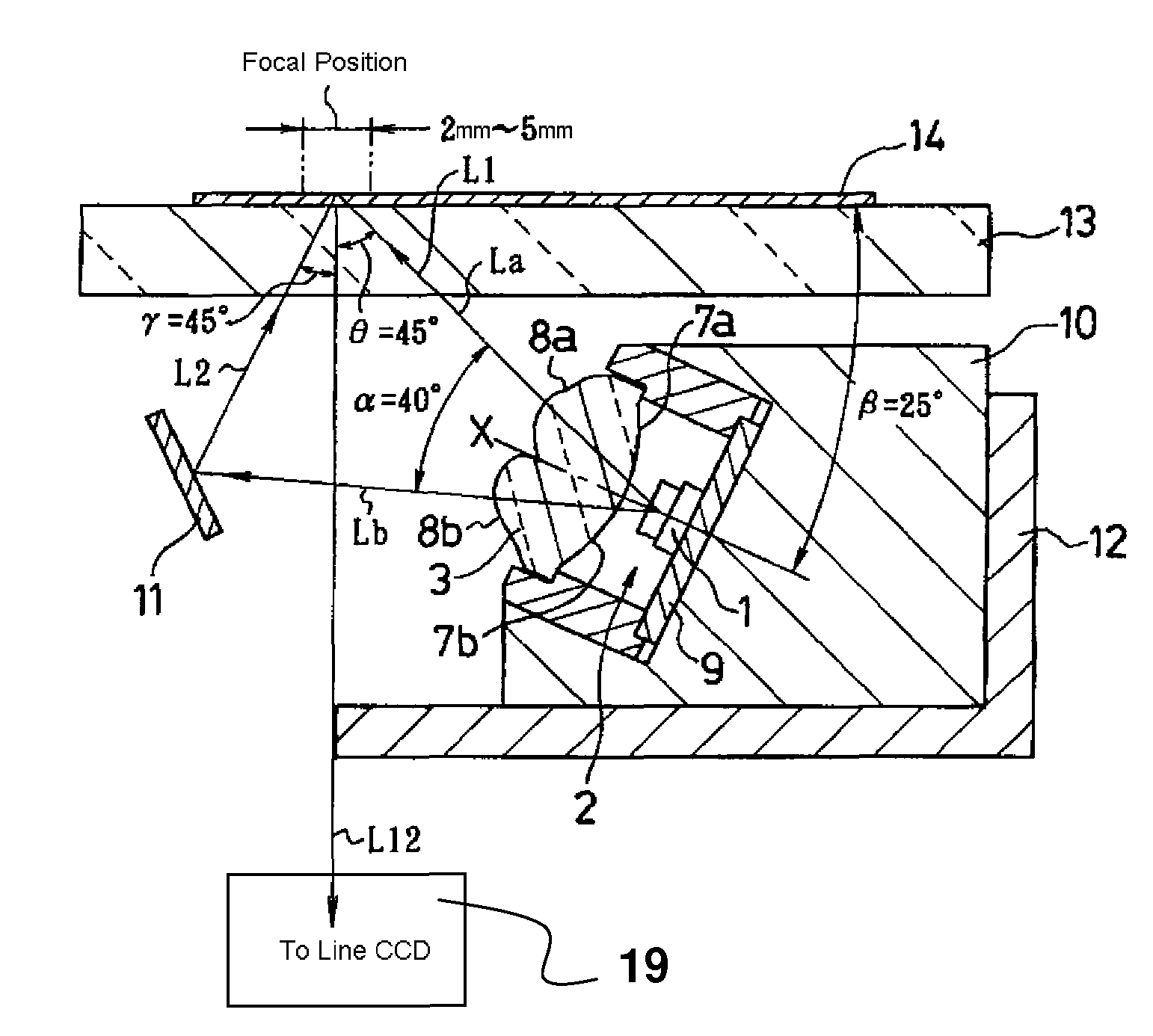
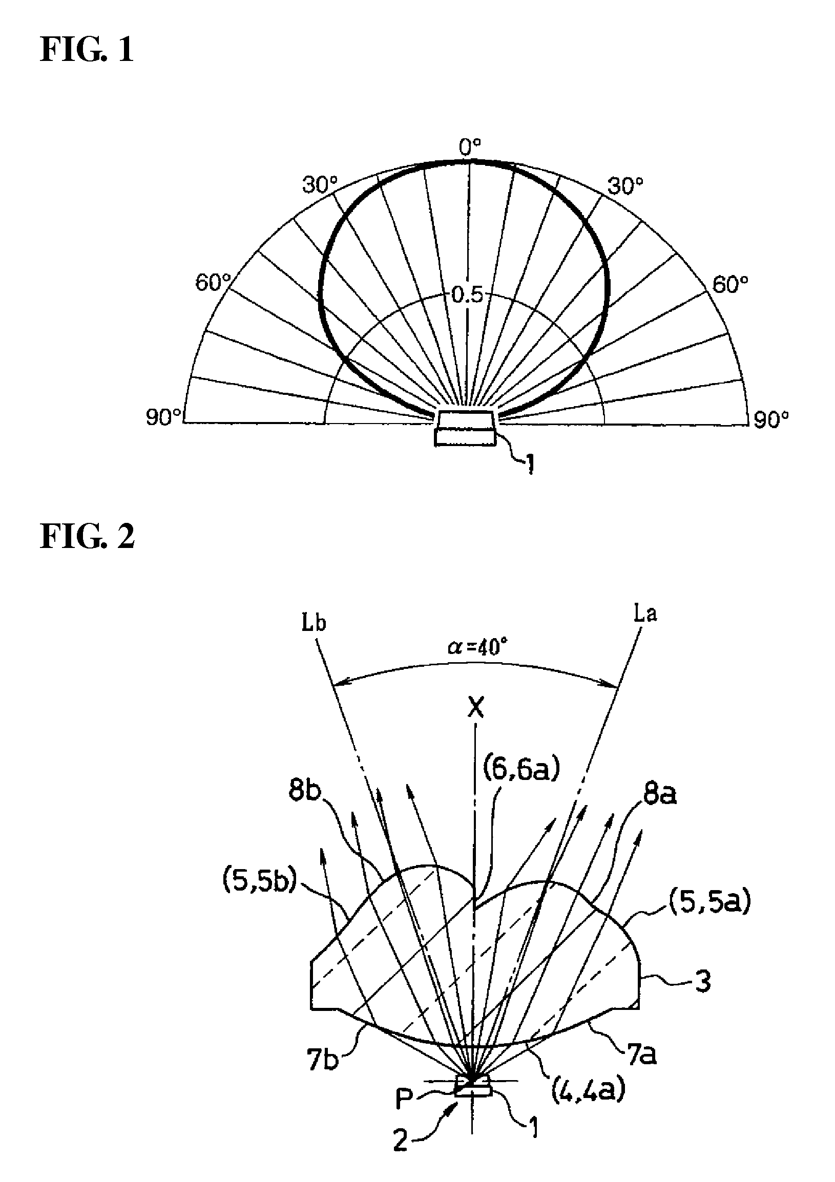
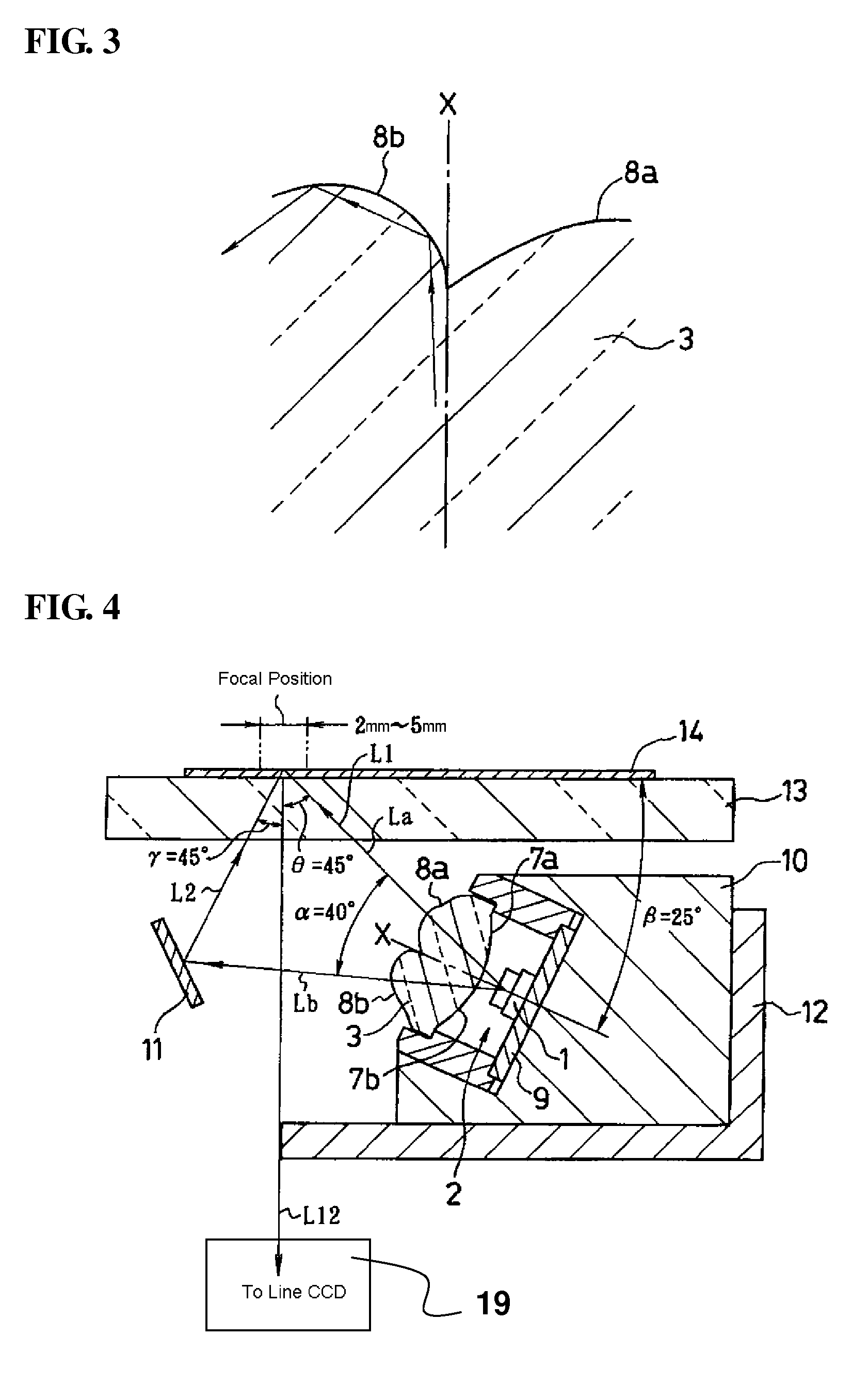
[0037]Certain exemplary embodiments of the disclosed subject matter will now be described in detail with reference to FIGS. 1-6 (with the same reference numerals denoting the same or similar elements). The below-described embodiments are suitable specific examples of the disclosed subject matter and include various technical features. The scope of the disclosed subject matter is, though, not limited to these embodiments.

[0038]An example of a light source unit of the disclosed subject matter can include a line light source including a plurality of LEDs arranged in line. Each of the LEDs is a white LED that emits light having a spectrum including wavelength components of red, green and blue light contained in three primary colors of light.

[0039]A blue LED element (chip) operative to emit blue light may be used as a light-emitting source. In this case, a specific configuration for the white LED comprises a blue LED element, a red fluorescent substance operative to provide a wavelength-...


PUM


Abstract

A light source unit and reader can include a line light source that is attached to a radiator and a rod lens that is attached above the line light source. The radiator with the line light source and the rod lens attached thereto, and a linear strip-shaped reflector arranged in front of the rod lens, are housed in a carriage. The carriage is supported beneath a contact glass and movable in a direction normal to a longitudinal axis of the line light source. The lens has a section in a plane normal to a longitudinal axis of the lens, in which a surface of the lens facing the light source has a curved line that expands or is convexly facing toward the light source. The opposite surface of the lens from the light source has composite curves including a plurality of continuous curves with different radii of curvature. The composite curves are located on both sides of a plane containing the optical axis of the LED and expand or are convex in an opposite direction from the light source.

Description

[0001]This application claims the priority benefit under 35 U.S.C. §119 of Japanese Patent Application No. 2007-193500 filed on Jul. 25, 2007, which is hereby incorporated in its entirety by reference.BACKGROUND[0002]1. Technical Field[0003]The disclosed subject matter relates to a light source unit, and more particularly to a light source unit for reading objects in a reader, such as a scanner.[0004]2. Description of the Related Art[0005]In a conventional process for reading a document in a scanner with a shrinkage optical system or a contact optical system, a line-shaped scanning light having a certain width may be emitted or applied onto the document image. The reflected light or transmitted light is then image-formed on a line solid-state imaging device (line CCD) through an optical path including mirrors and lenses. The output signal from the line solid-state imaging device (line CCD) is processed to read the document image.[0006]Among conventional devices, there has been propo...

Claims


Application Information

Patent Timeline
Patent Type & Authority Patents(United States)
IPC IPC(8): H04N1/04G03B27/54
CPCH04N1/02815H04N1/0285H04N1/02865H04N1/02885H04N1/02895H04N1/193
Inventor KANEKO, IKUO
Owner STANLEY ELECTRIC CO LTD
Why Eureka
Try Eureka