Electrode device for gas discharge sources and method of operating a gas discharge source having this electrode device

a technology of electrode devices and gas discharge sources, which is applied in the direction of discharge tube main electrodes, gas-filled discharge tubes, x-ray tubes, etc., can solve the problems of limited rotational frequency of electrode wheels, short circuits in lamps, lamp failures, etc., and achieve stable operation, higher rotational frequency, and higher output power

Active Publication Date: 2011-10-18
USHIO DENKI KK
View PDF5 Cites 11 Cited by
  • Summary
  • Abstract
  • Description
  • Claims
  • Application Information

AI Technical Summary

Benefits of technology

[0005]It is an object of the present invention to provide an electrode device for use in a gas discharge source as well as a method for operating a gas discharge source with such an electrode device, which allow a stable operation at higher rotational frequencies to achieve a higher output power.
[0007]The proposed electrode device at least comprises an electrode wheel rotatable around a rotational axis, said electrode wheel having an outer circumferential surface between two side surfaces, and a wiper unit arranged to limit the thickness of a liquid material film applied to at least a portion of said outer circumferential surface during rotation of said electrode wheel. The wiper unit is arranged and designed to form a gap between said outer circumferential surface and a wiping edge of the wiper unit and to inhibit or at least reduce a migration of liquid material from said side surfaces to the circumferential surface during rotation of the electrode wheel.
[0008]It has been found that the electrode wheel of such an electrode device, compared to the known electrode device disclosed in WO 2005 / 025280 A2, can be rotated at higher rotational speeds due to the wiper unit which inhibits or at least reduces a flow of liquid material from the side surfaces of the wheel to the outer circumferential surface. Such a measure is not realized with the wiper of WO 2005 / 025280 A2, which only controls the film thickness on the outer circumferential surface. The reduction of this flow or migration allows an improved control of the total amount of liquid material on the outer circumferential surface of the wheel and its distribution on this surface. Therefore, the thickness of the liquid material film on the rotating electrode wheel can be effectively limited even at higher rotational speeds to form a stable film which is maintained with sufficient thickness at the discharge region. With this measure higher rotational speeds are achieved compared to electrode devices which do not have such a wiper unit suppressing or reducing the migration of liquid material from the side surfaces to the outer circumferential surface and reducing the amount of liquid metal on the circumferential surface.
[0011]Although in the above examples or preferred embodiments one of the wiper elements is designed to form the gap and at the same time to strip off liquid material from the side surfaces of the electrode wheel, it is also possible to use one of the wiper elements to form the gap and one or several further wiper elements to strip off liquid material at portions of the side surfaces of the electrode wheel. Furthermore, several wiper units may be arranged at different positions of the circumferential surface with respect to the rotational direction in order to further improve the shaping of the liquid material film on the circumferential surface. Preferably such a further wiper unit is designed similar to the main wiper unit, having one or several wiper elements limiting the thickness of the liquid material film on the surfaces of the wheel. Said further wiper unit is then arranged in a rotational direction before said main wiper unit.
[0012]Preferably further measures are taken to reduce the amount of liquid material which may migrate during rotation of the electrode wheel from the side surfaces to the circumferential surface. One of these measures is to use an electrode wheel which has a T-shaped cross section at the outer circumferential surface. Due to this T-shaped form the liquid material can not access the outer circumferential surface on a straight way but has to move around a protrusion. A further preferable measure is to apply a non-wetting layer or coating on the side surfaces of the electrode wheel. It goes without saying that the outer circumferential surface on the other hand must consist of a wetting material or be coated with such a material.
[0014]In order to allow an optimal adjustment of the gap for controlling the film thickness of the liquid material on the outer circumferential surface, the distance of the wiping edge defining this gap and the outer circumferential surface of the electrode wheel is preferable adjustable by using an adjustable wiper element. This allows the proper setting of the gap dependent on the rotational frequency and the properties of the liquid material used when operating the gas discharge source.

Problems solved by technology

These droplets can cause short circuits in the lamp and thus lamp failure.
Nevertheless, the rotational frequency of the electrode wheels is limited due to the formation of droplets or instabilities of the liquid metal film at higher rotational speeds.

Method used


Image

  • Electrode device for gas discharge sources and method of operating a gas discharge source having this electrode device
  • Electrode device for gas discharge sources and method of operating a gas discharge source having this electrode device
  • Electrode device for gas discharge sources and method of operating a gas discharge source having this electrode device

Examples


Embodiment Construction

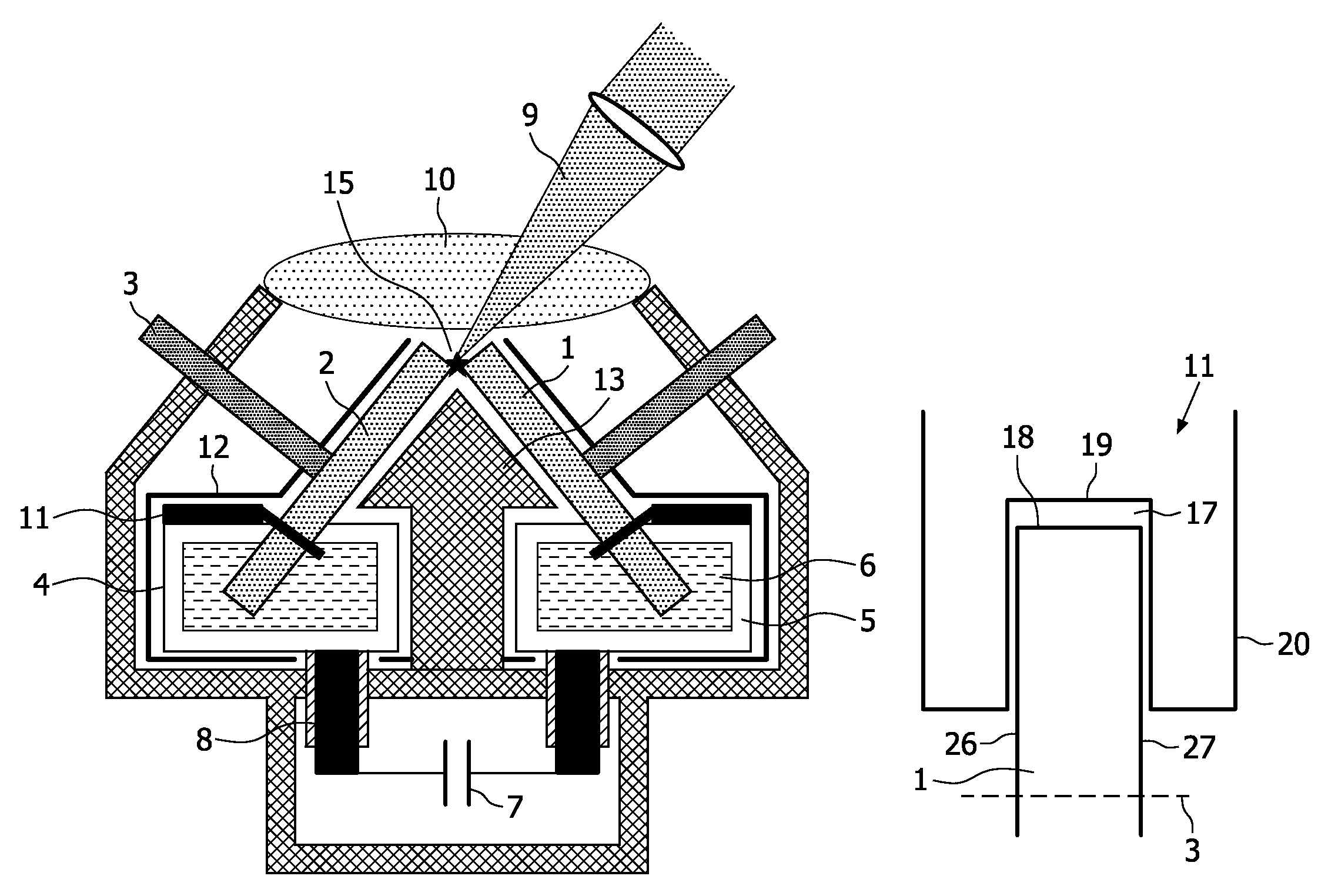
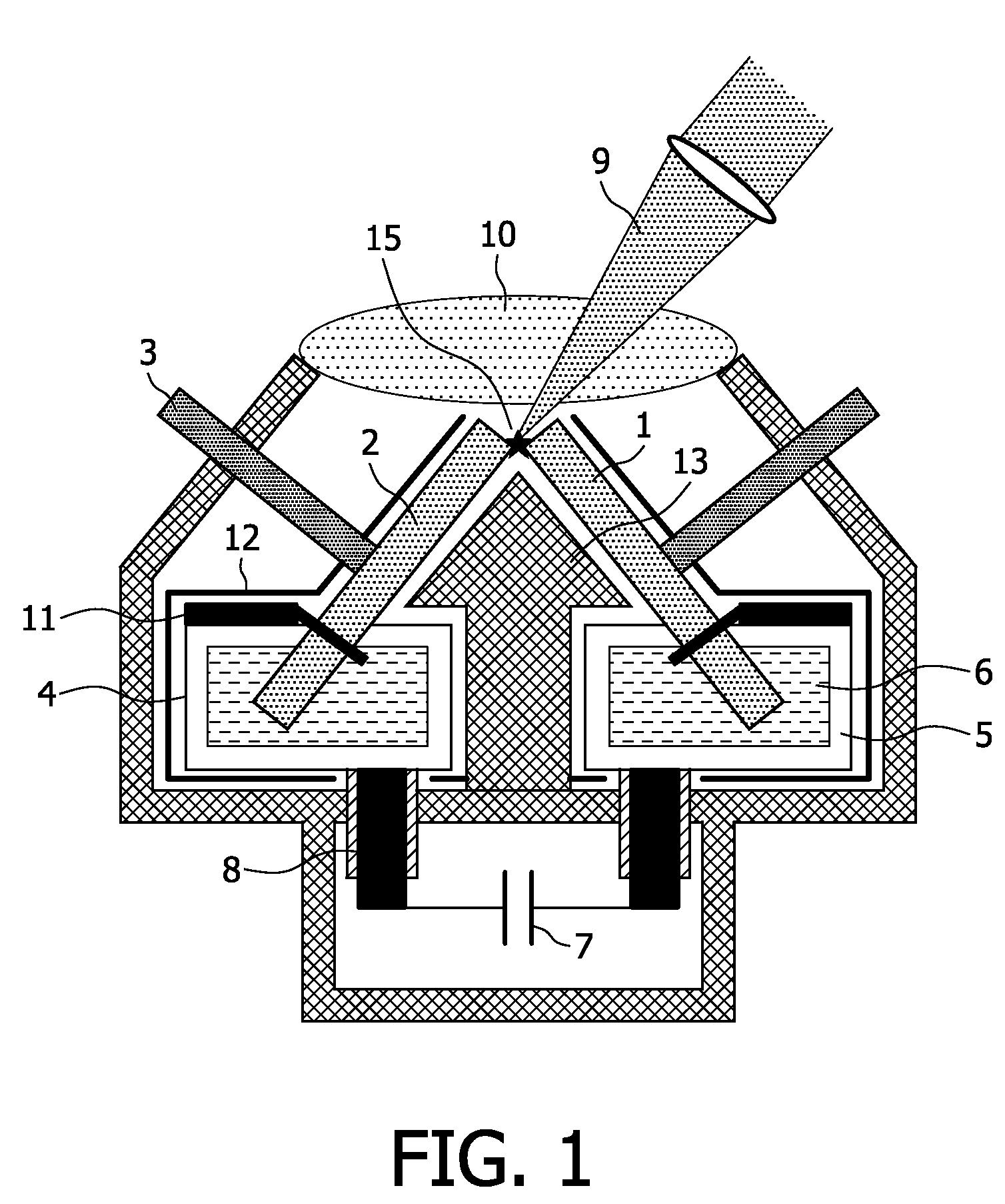
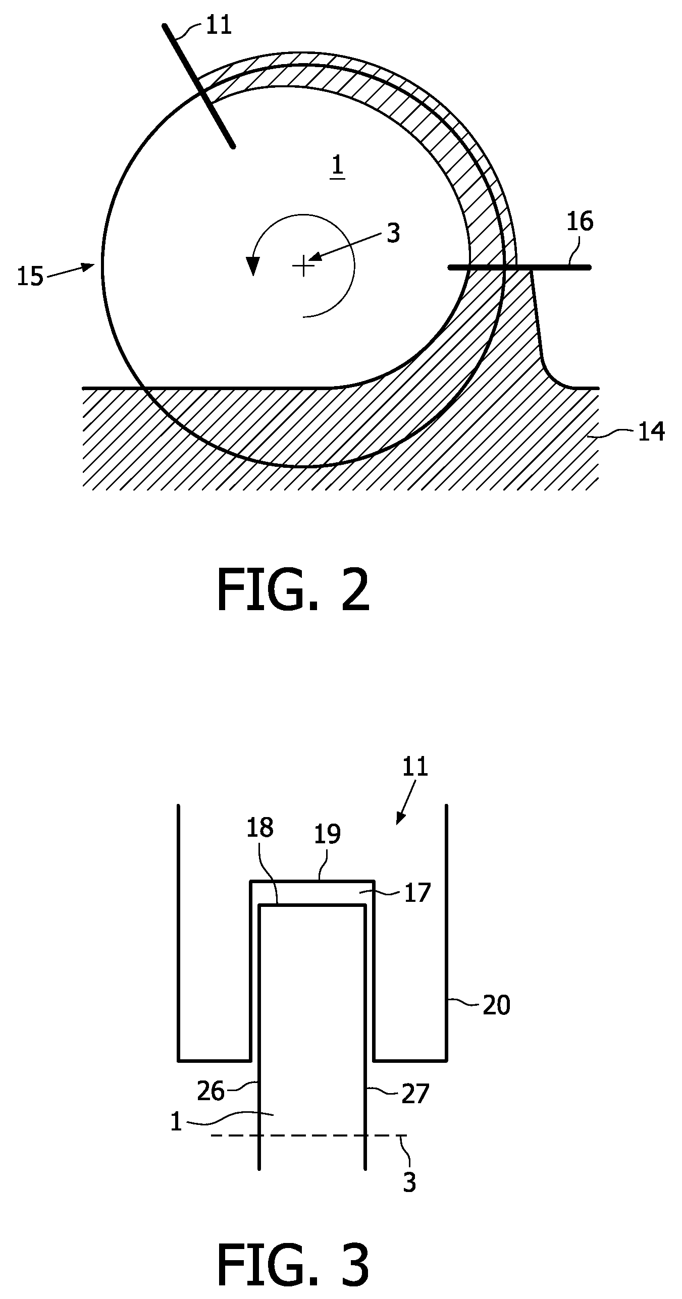
[0031]FIG. 1 shows a schematic side view of a pulsed gas discharge source, in which an electrode device according to the present invention may be implemented. Details of this electrode device are not shown in the figure. The gas discharge source comprises the two electrodes 1, 2 arranged in a discharge space of pre-definable gas pressure. The wheel shaped electrodes 1, 2 are rotatable mounted, i.e. they are rotated during operation about a rotational axis 3. During rotation the electrodes 1, 2 partially dip into corresponding containers 4, 5. Each of these containers4, 5 contains a metal melt 6, in the present case liquid tin. The metal melt 6 is kept on a temperature of approximately 300° C., i.e. slightly above the melting point of 230° C. of tin. The metal melt in the containers 4, 5 is maintained at the above operation temperature by a heating device or a cooling device (not shown in the figure) connected to said containers. During rotation the outer circumferential surfaces of ...


PUM


Abstract

The present invention relates to an electrode device for gas discharge sources, a gas discharge source comprising such an electrode device and to a method of operating the gas discharge source. The electrode device comprises an electrode wheel (1) rotatable around a rotational axis (3) and a wiper unit (11) arranged to limit the thickness of a liquid material film applied to at least a portion of an outer circumferential surface (18) of the electrode wheel (1) during rotation of said electrode wheel (1). The wiper unit (11) is arranged and designed to form a gap (17) between the outer circumferential surface (18) and a wiping edge (19) of the wiper unit (11) and to inhibit or at least reduce a migration of liquid material from side surfaces to the outer circumferential surface (18) of the electrode wheel (1) during rotation. With the proposed electrode device the electrode wheel (1) can be rotated at higher rotational speeds without the formation of droplets resulting in a higher output power and pulse frequency of a gas discharge source having such an electrode device.

Description

FIELD OF THE INVENTION[0001]The present invention relates to an electrode device for gas discharge sources at least comprising an electrode wheel rotatable around a rotational axis, said electrode wheel having an outer circumferential surface between two side surfaces, and a wiper unit arranged to limit the thickness of a liquid material film applied to at least a portion of said outer circumferential surface during rotation of said electrode wheel. The invention further relates to a gas discharge source comprising such an electrode device and to a method of operating the gas discharge source with this electrode device.BACKGROUND OF THE INVENTION[0002]Gas discharge sources are used, for example, as light sources for EUV radiation (EUV: extreme ultra violet) or soft x-rays. Radiation sources emitting EUV radiation and / or soft x-rays are in particular required in the field of EUV lithography. The radiation is emitted from hot plasma produced by a pulsed current. The most powerful EUV ...

Claims


Application Information

Patent Timeline
Patent Type & Authority Patents(United States)
IPC IPC(8): H05G2/00H01J1/02
CPCH05G2/005H05G2/003
Inventor ZHOKHAVETS, ULADZIMIRKRUECKEN, THOMASDERRA, GUENTHER HANS
Owner USHIO DENKI KK
Why Eureka
Try Eureka