Liquid crystal display device and manufacturing method of liquid crystal display device
a technology of liquid crystal display device and manufacturing method, which is applied in the direction of conveyors, radio frequency controlled devices, instruments, etc., can solve the problems of plastic substrate and resin that have not enough heat resistance to withstand heat treatment, and achieve the effects of reducing weight, reducing space for using ic, and reducing weigh
- Summary
- Abstract
- Description
- Claims
- Application Information
AI Technical Summary
Benefits of technology
Problems solved by technology
Method used
Image

Examples
example 1
[0163]The case that the present invention is applied to a card as typified by an electronic card will be explained in this example.
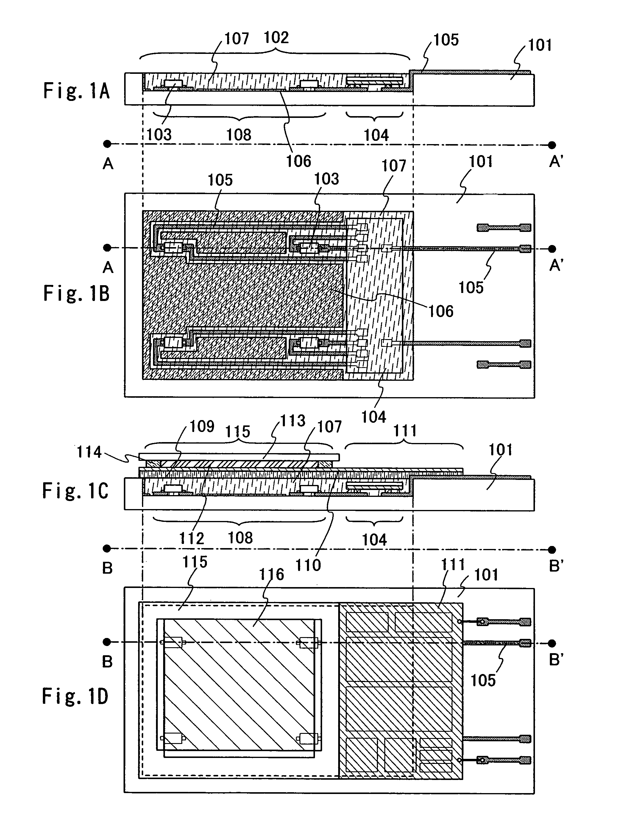
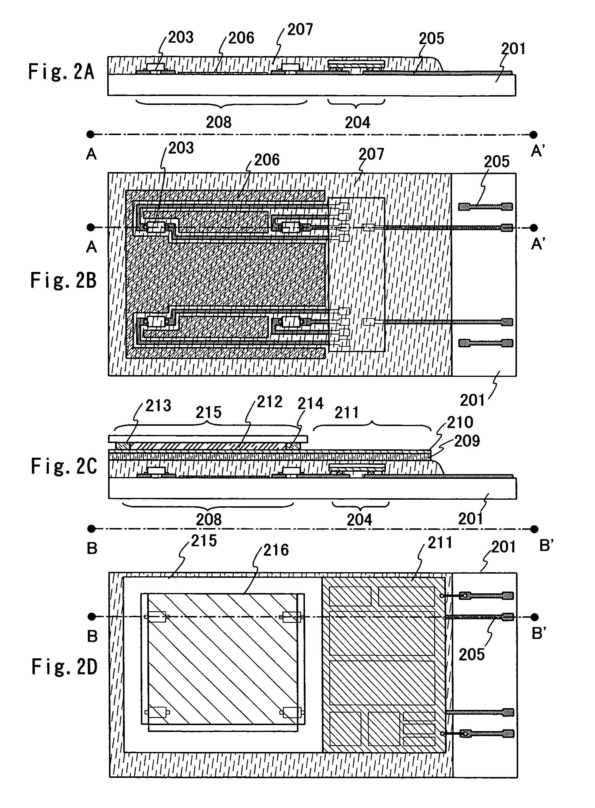
[0164]The configuration of an electronic card according to this example will be explained with reference to FIGS. 13A to 13D. FIG. 13A is a cross-sectional view showing a device substrate 401 at the time that a panel is completed. FIG. 13B is a top surface view of the device substrate illustrated in FIG. 13A. FIG. 13A shows the state that is taken along the line of A-A′.
[0165]The device substrate 401 illustrated in FIGS. 13A and 13B has a concave portion 402 in which an LED 403 or a plurality of those is formed. An LED driver thin film circuit 404 is provided to the concave portion 402. The LED 403 and the LED driver circuit are covered with a resin 407.
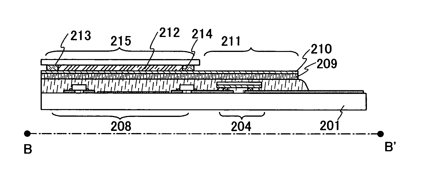
[0166]Reference numeral 415 denotes a panel, and 411 denotes a thin film circuit. The panel and the thin film circuit are formed separately and pasted onto the device substrate 401. The thin film circuit ...
example 2
[0171]A method for manufacturing a plurality of liquid crystal display apparatus from a large sized device substrate will be explained with reference to FIGS. 14A and 14B.
[0172]A shown in FIGS. 14A and 14B, in case of using a large sized device substrate 601, a plurality of concave portions 603 is formed in areas 602, each of which is corresponding to each liquid crystal display apparatus. LEDs 604 are provided in each concave portion 603. A wiring connected electrically to the LED 604, an LED driver thin film circuit, a reflection film, or the like (all are not shown) are provided with the LEDs, and a resin 605 is filled with each concave portion 603 as shown in FIG. 14B.
[0173]A panel or a thin film circuit is formed and diced in accordance with the method explained in the embodiment, and a plurality of liquid crystal display apparatus can be manufactured from one device substrate. The dicing can be carried out either before or after forming the panel or the thin film circuit.
example 3
[0174]In this embodiment, the example that an LED is connected to a flexible printed wiring board (FPC) and the FPC is connected to a wiring over a device substrate, instead that the LED is directly connected to the wiring over a device substrate.
[0175]FIG. 15A is a top surface view of an FPC connected with an LED. An LED 701 is connected to a lead 702 that is sandwiched by a plastic film 703. A terminal 704 connected with the lead 702 is not covered with the plastic film 703 and is exposed.
[0176]FIG. 15B is a view showing the state that the LED 701 illustrated in FIG. 15A is pasted onto a concave portion 705 in the device substrate 706. FIG. 15C is a view showing a reverse side of the device substrate 706 illustrated in FIG. 15B.
[0177]In the device substrate 706, a wiring 707 is provided with a reverse side of the concave portion 705. The LED 701 provided in the concave portion 705 and the wiring 707 are electrically connected each other by the lead 702.
[0178]The surface of the dev...
PUM
| Property | Measurement | Unit |
|---|---|---|
| weight | aaaaa | aaaaa |
| thickness | aaaaa | aaaaa |
| thickness | aaaaa | aaaaa |
Abstract
Description
Claims
Application Information
 - R&D
- Intellectual Property
- Life Sciences
- Materials
- Tech Scout
- Unparalleled Data Quality
- Higher Quality Content
- 60% Fewer Hallucinations
Browse by: Latest US Patents, China's latest patents, Technical Efficacy Thesaurus, Application Domain, Technology Topic, Popular Technical Reports.
© 2025 PatSnap. All rights reserved.Legal|Privacy policy|Modern Slavery Act Transparency Statement|Sitemap|About US| Contact US: help@patsnap.com