
Post-process sizing control device for grinding machine

a technology of sizing control and grinding machine, which is applied in the direction of process and machine control, program control, instruments, etc., can solve the problems of reducing productivity and elongating achieves shortening the machining cycle time, improving productivity, and efficient post-process sizing control

Inactive Publication Date: 2011-10-18
JTEKT CORP
View PDF6 Cites 2 Cited by
  • Summary
  • Abstract
  • Description
  • Claims
  • Application Information

AI Technical Summary

Benefits of technology

[0008]It is therefore an object of the present invention to provide an improved post-process sizing control device capable of controllably switching size measuring intervals for sizing control in dependence on the state in grinding operation of the grinding machine.
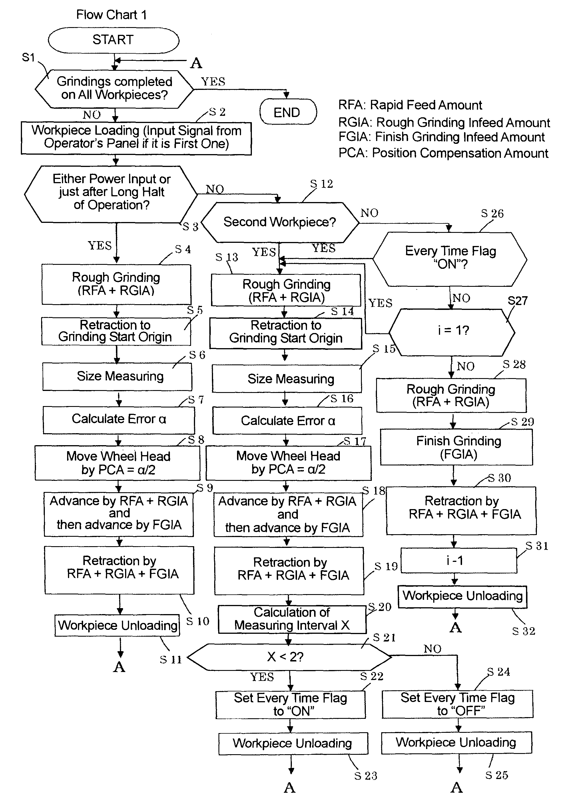
[0010]With this construction, in setting the number of workpieces which should be ground during the next size measuring interval which begins after the preceding position compensation operation and ends with the next position compensation operation, the number of workpieces ground during the next size measuring interval is set based on the average position compensation amount derived by dividing the position compensation amount which the origin compensation means determines for the last workpiece during the present size measuring interval, by the number of workpieces ground during the present size measuring interval. Therefore, the next size measuring interval for sizing control can be set in dependence on the latest state of the grinding machine during the present size measuring interval, and any unnecessary measuring for sizing control can be prevented from being carried out, so that it becomes possible to efficiently perform the post-process sizing control and to improve the productivity through the shortening of the machining cycle time.
[0012]With this construction, in setting the number of workpieces which should be ground during the next size measuring interval which begins after the preceding position compensation operation and ends with the next position compensation operation, the number of workpieces ground during the next size measuring interval is set based on the average position compensation amount difference derived by dividing the difference between position compensation amounts which the wheel head origin compensation means determines respectively for the last workpieces ground during the preceding and present size measuring intervals, by the number of workpieces ground during the present size measuring interval. Therefore, the next size measuring interval for sizing control can be set in dependence on the latest state of the grinding machine during the present size measuring interval, and any unnecessary measuring for sizing control can be prevented from being carried out, so that it becomes possible to efficiently perform the post-process sizing control and to improve the productivity through the shortening of the machining cycle time.

Problems solved by technology

However, in the foregoing post-process sizing control device, the post-process sizing control is carried out at the size measuring intervals which have been set in advance, and no considerations are given to machine-dependant differences, the fluctuation in the ambient temperature, the length of the duration in which the grinding machine has been kept in the stop state.
This causes the machining cycle time to be elongated and hence, the productivity to decline.

Method used


Image

  • Post-process sizing control device for grinding machine
  • Post-process sizing control device for grinding machine
  • Post-process sizing control device for grinding machine

Examples


first embodiment

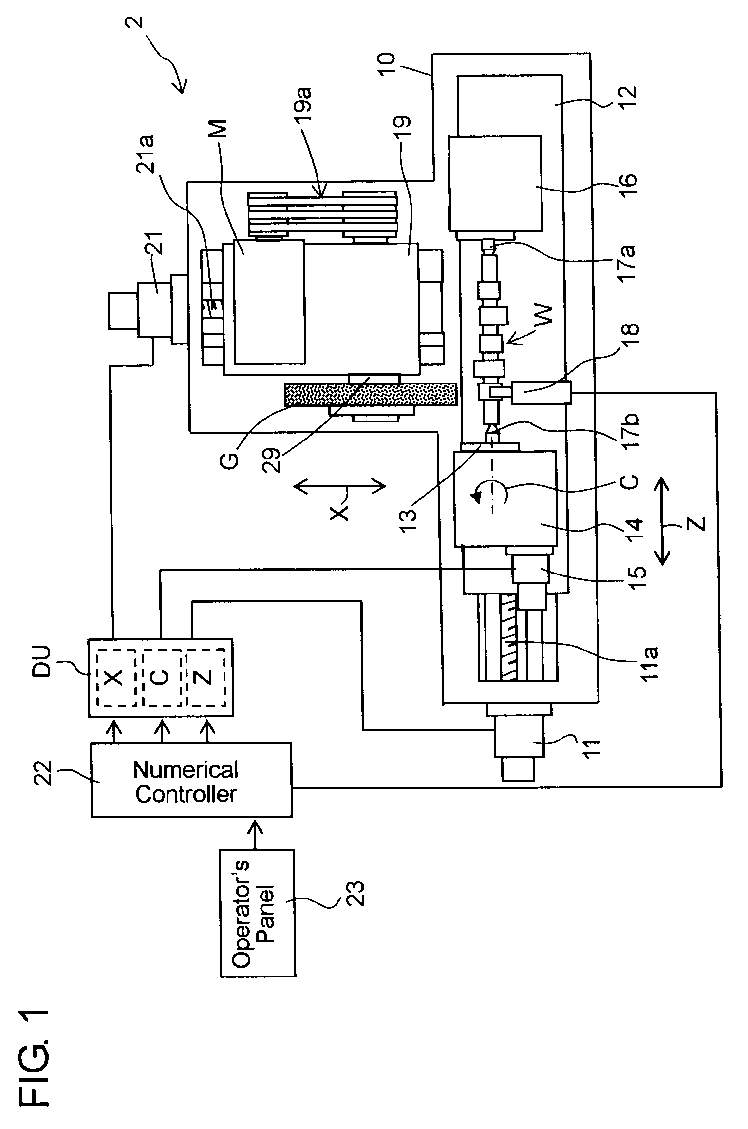
[0022]Hereafter, a post-process sizing control in a first embodiment according to the present invention will be described in detail with reference to the accompanying drawings. Referring now to FIG. 1, a work table 12 which is driven by a servomotor 11 through a feed screw mechanism 11a is mounted on a bed 10 of a numerical control grinding machine 2 slidably in a Z-axis direction parallel to a work spindle axis. A work head 14 rotatably carrying a work spindle 13 is mounted on the work table 12, and the work spindle 13 is rotatable about a C-axis as the work spindle axis by a work spindle servomotor 15 mounted on the work head 14. A foot stock 16 is mounted on the right side of the work table 12 as viewed in FIG. 1. A workpiece W with non-circular portions thereon is rotatably supported by a center 17a on the foot stock 16 and a center 17b on the work spindle 13.

[0023]A wheel head 19 is mounted on the rear part of the bed 10 and is guided to be movable toward and away from the work...

second embodiment

[0039]In the foregoing first embodiment, each time the post-process sizing control is performed in the course of successive grindings of the workpieces, the grinding start origin is altered by the foregoing α / 2 to shift the position of the wheel head 19, and the wheel head 19 is retracted to the compensated grinding start origin in the retraction feed. In a second embodiment described below, on the contrary, the grinding start origin is not altered, wherein the wheel head 19 is retracted to the initial grinding start origin whenever retracted.

[0040]The operation of the post-process sizing control in the second embodiment will be described with reference to a flow chart 2 shown in FIG. 4. One of the differences from the first embodiment is that after the rough infeed is completed by the first part of the rough grinding infeed amount, the wheel head 19 is not moved for position compensation between steps S40 and S41 as well as between steps S48 and S49.

[0041]Other differences are that...

third embodiment

[0043]In the foregoing first and second embodiments, description has been made regarding the case that workpieces each having one non-circular portion are ground successively. However, the present invention can equally applicable to one cylindrical grinding machine for successively grinding a plurality of workpieces each having a cylindrical portion to be ground. The cylindrical grinding machine to which the present invention is applied will be described hereafter as a third embodiment. In the third embodiment, the differences from the foregoing first embodiment will be described, while the same constructions and functions as those of the first embodiment will be omitted from being described in detail.

[0044]It has heretofore been practiced to perform a so-called “in-process sizing control” wherein the size of a workpiece is measured at the same time as the grinding operation of the workpiece. The in-process sizing control is known as a grinding method in which a wheel head is moved ...


PUM

PropertyMeasurementUnit
timeaaaaaaaaaa
size measuringaaaaaaaaaa
sizeaaaaaaaaaa

Abstract

A post-process sizing control device is provided with origin compensation means for controlling a size measuring device to measure an actual size of a workpiece portion and for compensating the origin of a wheel head by a position compensation amount which corresponds to a difference between the actual size and a theoretical size derived from calculation and size measuring interval setting means for setting the number of workpieces which should be ground during the next size measuring interval which begins after the preceding origin compensation operation and ends with the next origin compensation operation. The size measuring interval setting means sets the number of workpieces which should be ground during the next size measuring interval, based on an average position compensation amount derived by dividing a position compensation amount for the last workpiece ground during the present size measuring interval by the number of workpieces ground during the present size measuring interval.

Description

INCORPORATION BY REFERENCE[0001]This application is based on and claims priority under 35 U.S.C. 119 with respect to Japanese patent application No. 2008-092988 filed on Mar. 31, 2008, the entire content of which is incorporated herein by reference.BACKGROUND OF THE INVENTION[0002]1. Field of the Invention[0003]The present invention relates to a post-process sizing control device for measuring a machining portion of a workpiece to control a further infeed amount of a grinding wheel against the machining portion in a grinding machine.[0004]2. Discussion of the Related Art[0005]Generally, for grinding a workpiece, there has been used a numerically controllable grinding apparatus (numerical control grinding machine), wherein the workpiece is rotatably mounted on a work spindle and wherein the feed amount of a wheel head movable in a direction intersecting with the work spindle is controlled in synchronous relation with the rotation of the work spindle to perform a grinding operation. A...

Claims


Application Information

Patent Timeline
Patent Type & Authority Patents(United States)
IPC IPC(8): G06F19/00B24B49/00B24B7/00B24B51/00B24B7/30B24B19/12B24B49/03
CPCB23Q17/20B24B19/125B24B49/03G05B19/401B24B5/04G05B2219/45218G05B2219/37576
Inventor INOUE, MASAHARUYAMAGUCHI, TOMOHISA
Owner JTEKT CORP
Learn More