
Method of gear-shifting in a servo-controlled manual gearbox

a servo-controlled, gear-shifting technology, applied in the direction of digital data processing details, mechanical equipment, instruments, etc., can solve the problems of 250 ms gear shift already very fast, vehicle transmission subjected to unnecessary mechanical strain, damage to transmission itself, etc., to achieve rapid gear shift, easy and cost-effective implementation

Active Publication Date: 2011-10-18
SPAN FERRARI SPA
View PDF8 Cites 7 Cited by
  • Summary
  • Abstract
  • Description
  • Claims
  • Application Information

AI Technical Summary

Benefits of technology

This approach allows for extremely short gear shifting times, reducing mechanical strain and costs, while maintaining compatibility with comfort and mechanical protection requirements, enabling faster gear transitions without the need for expensive braking systems or complex control mechanisms.

Problems solved by technology

In normal driving conditions, the servo-controlled gearbox is required to rapidly shift gears without triggering abrupt longitudinal acceleration / deceleration on the vehicle, which are annoying for vehicle passengers and subject the vehicle transmission to unnecessary mechanical strain.
In sporty driving conditions, the servo-controlled gearbox is required to shift gears as fast as possible without subjecting the transmission to excessive mechanical strain which could lead to damaging the transmission itself.
A 250 ms gear shift is already very fast; however, it is still relatively slow for sporty driving, especially for competitive track racing.
However, this solution is relatively costly and complicated due to the need of arranging and controlling a brake coupled to the primary gearbox shaft.
However, also the method proposed by patent application EP1201483, while reducing the required shifting time, does not allow to reach the extremely short shifting times required by sporty driving.

Method used


Image

  • Method of gear-shifting in a servo-controlled manual gearbox
  • Method of gear-shifting in a servo-controlled manual gearbox
  • Method of gear-shifting in a servo-controlled manual gearbox

Examples


Embodiment Construction

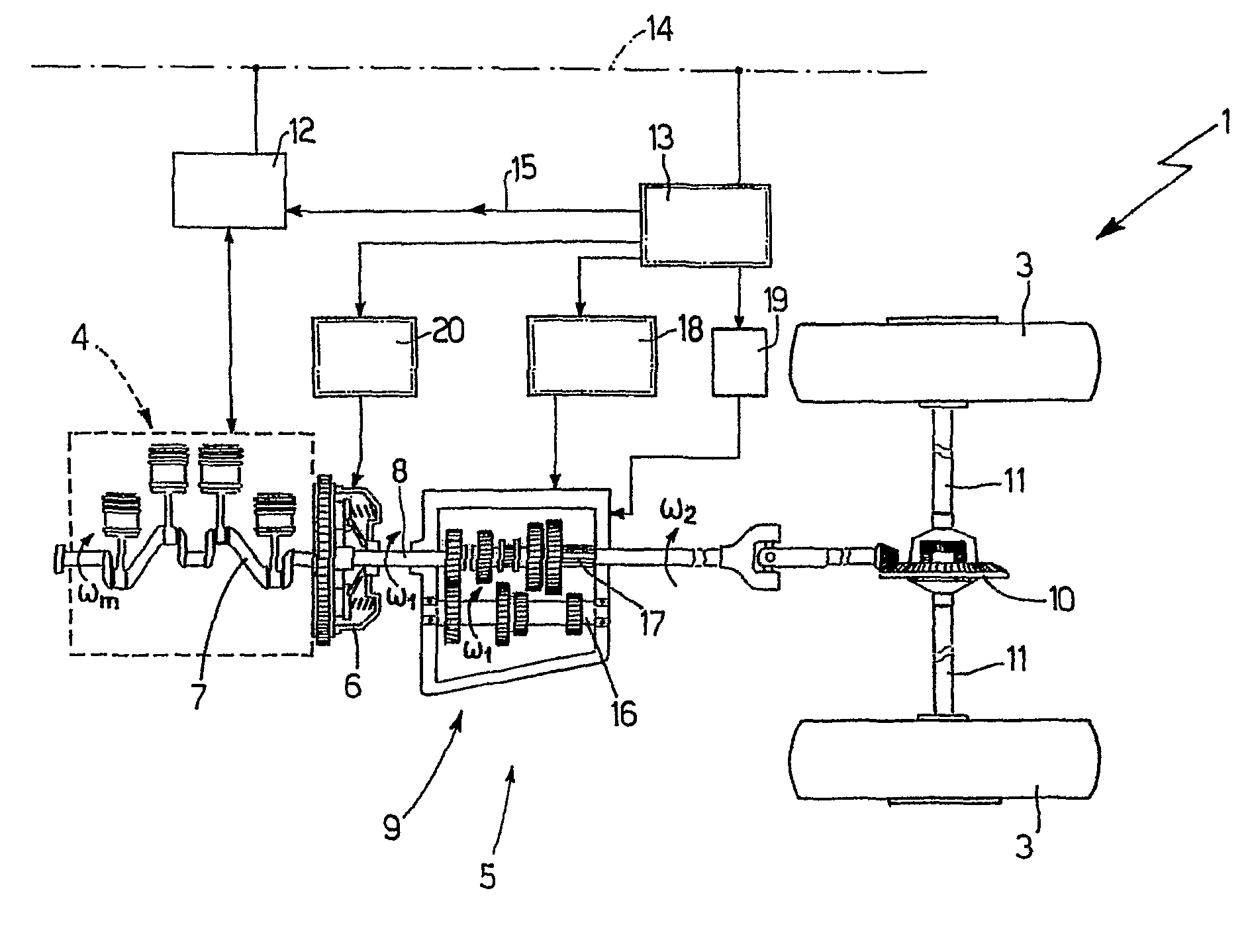
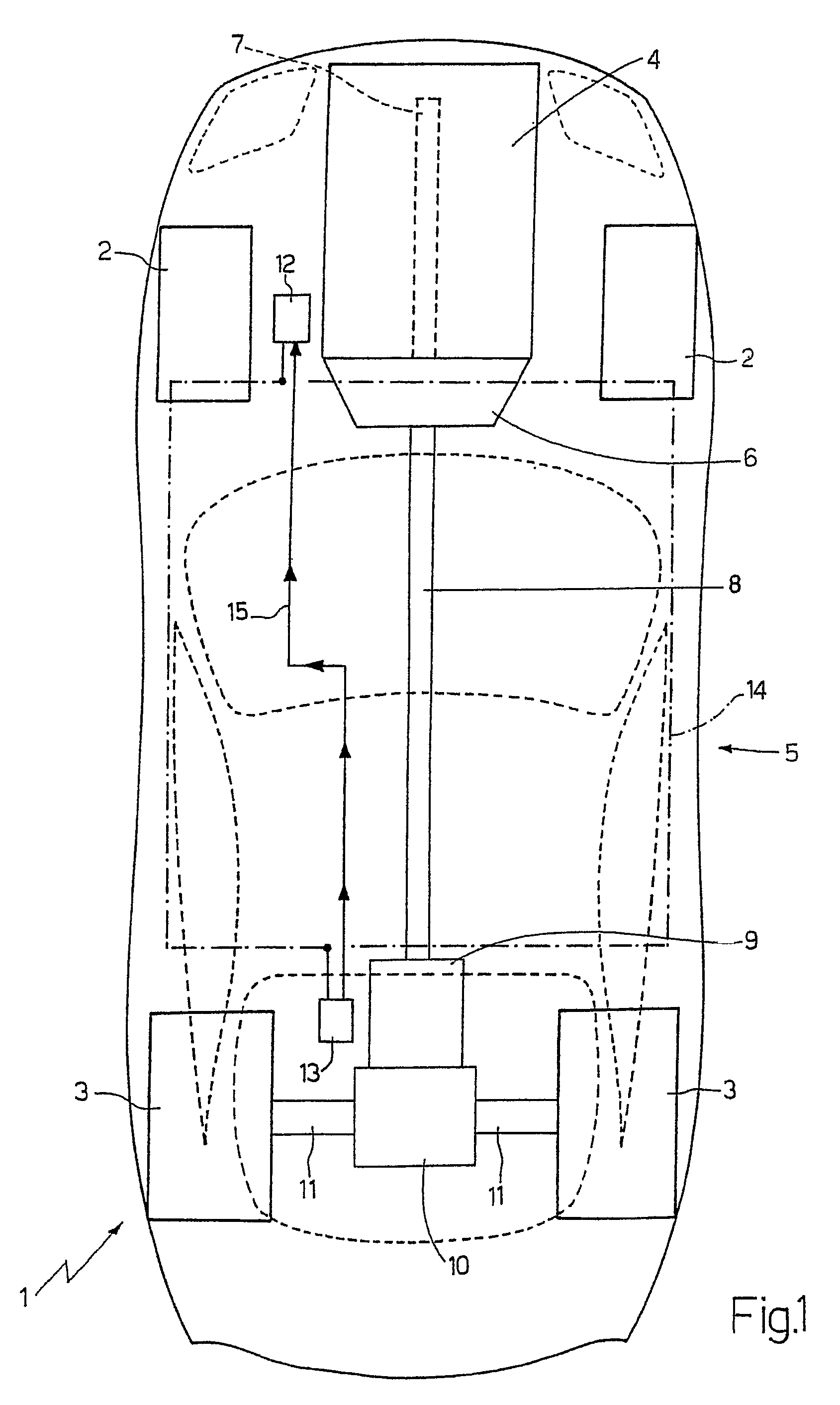
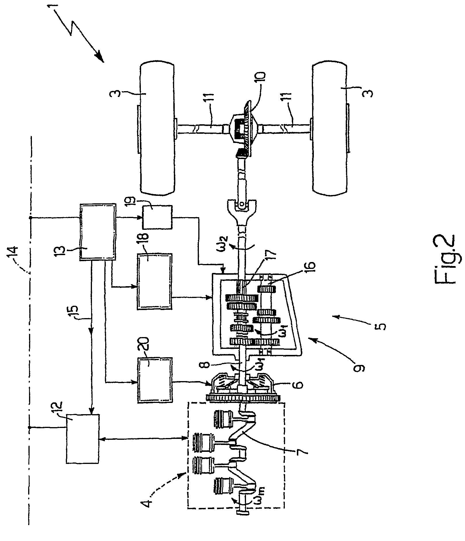
[0019]In FIG. 1, number 1 indicates a motor vehicle provided with two front wheels 2 and two rear drive wheels 3; an internal combustion engine 4, which produces a motive torque which is transmitted to rear drive wheels 3 by means of a transmission 5, is arranged in frontal position. Transmission 5 comprises a servo-assisted clutch 6, which is connected to a bell integral with engine 4 and adapted to connect crankshaft 7 of engine 4 to a propeller shaft 8 ending in a servo-assisted gearbox 9 arranged on the rear axle. A self-locking differential 10 is arranged in cascade to servo-assisted gearbox 9, from which differential a pair of drive axles 11 depart, each of which is integral with a rear drive wheel 3. Motor vehicle 1 comprises a control unit 12 of engine 4, a control unit 13 of transmission 5, and a BUS line 14, which is implemented according to the CAN (Car Area Network) protocol and spanned throughout the entire motor vehicle 1.

[0020]Both control unit 12 of engine 4, and con...


PUM


Abstract

A method of gear shifting in a servo-controlled gearbox. The method generates an oscillation on angular velocities of primary and secondary shafts of the gearbox, separates the primary shaft from the secondary shaft thus disengaging a first current gear when the oscillation has taken the angular velocity of the primary shaft close to the angular velocity that the primary shaft must assume to engage a second next gear, and connects the primary shaft to the secondary shaft thus engaging the second next gear when the oscillation has led the angular velocity of the secondary shaft to equalize the current angular velocity of the primary shaft multiplied by the transmission ratio of the second next gear.

Description

TECHNICAL FIELD[0001]The present invention relates to method and unit for gear-shifting in a servo-controlled gearbox.BACKGROUND ART[0002]There is an increasing use of servo-controlled gearboxes, which are structurally similar to manual gearboxes of the traditional type, except for the fact that the clutch pedal and the gear selection lever operated by the user are replaced by corresponding electrical or hydraulic servo-controls. When using a servo-controlled gearbox, the user only needs to send the order to shift up or down to a transmission control unit and the transmission control unit autonomously shifts by acting both on the engine and on the servo-controls associated to clutch and gearbox.[0003]The gear shifting order may be generated either manually, i.e. following a command imparted by the driver, or automatically, i.e. regardless of the action of the driver. When the gear shifting order is generated, the transmission control unit drives the servo-control associated to the c...

Claims


Application Information

Patent Timeline
Patent Type & Authority Patents(United States)
IPC IPC(8): G06F19/00F16H61/02B60W10/10B60W30/18
CPCB60W30/19F16H61/0403B60W10/02B60W10/06B60W10/11F16H2306/44F16H2306/50
Inventor BALDET, FRANCKPOGGIO, LUCAVISCONTI, AMEDEO
Owner SPAN FERRARI SPA
Learn More