

Specialized processing block for programmable logic device
- Summary
- Abstract
- Description
- Claims
- Application Information
AI Technical Summary
Benefits of technology
Problems solved by technology
Method used
Image

Examples
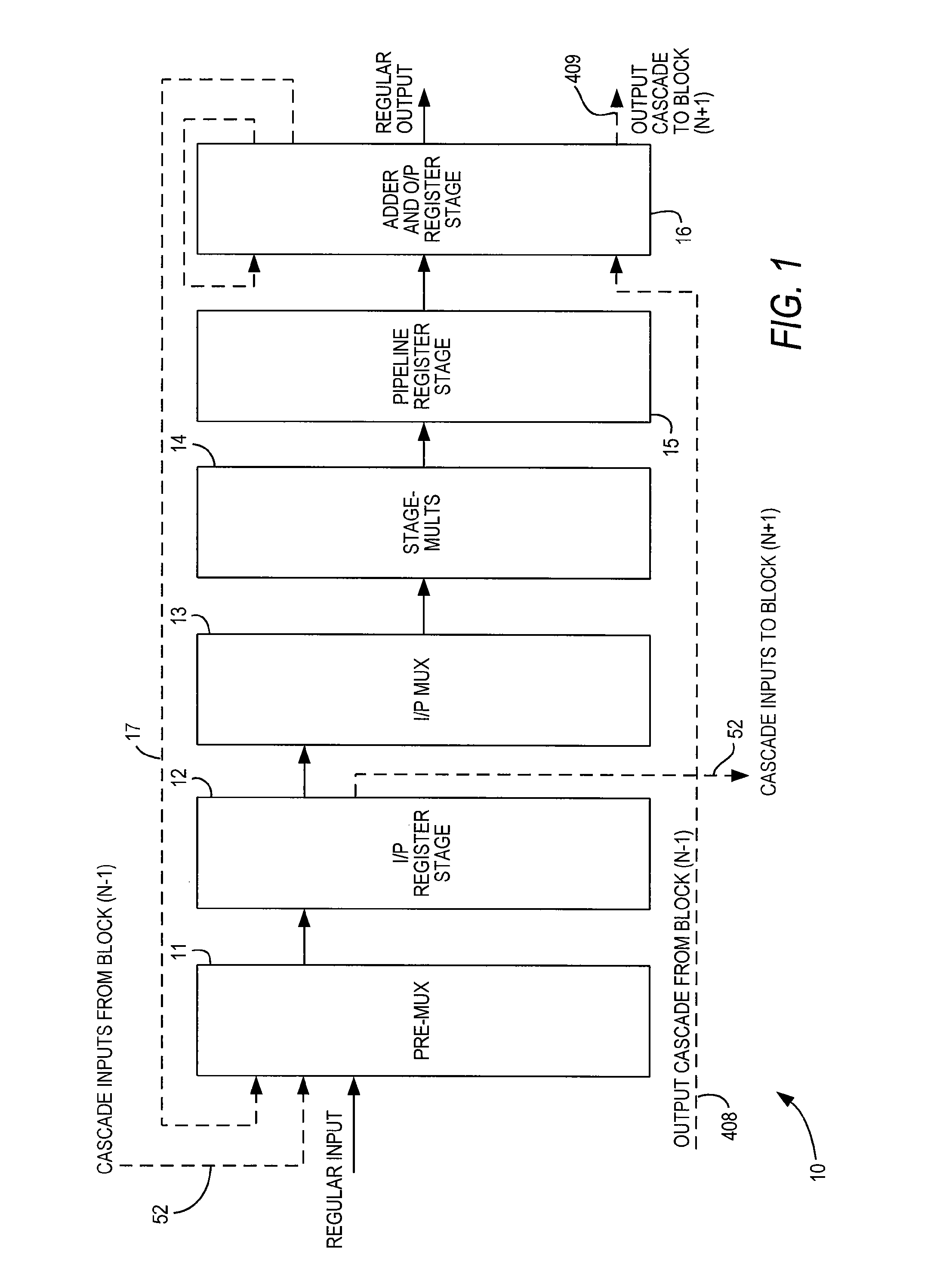
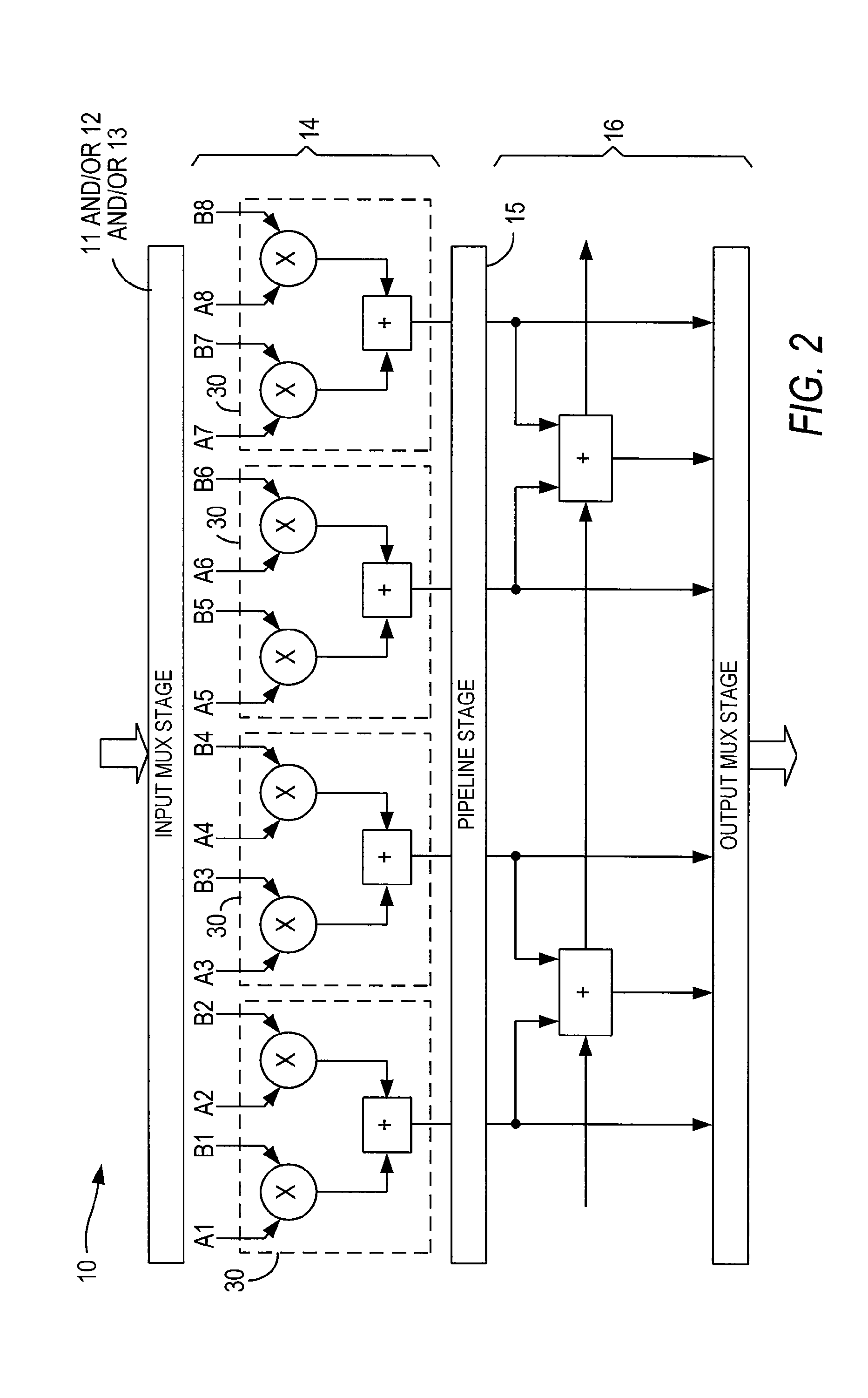
embodiment 10
[0048]FIG. 1 shows a high-level diagram of one preferred embodiment 10 of a specialized processing block according to the invention, while FIG. 2 is a functional diagram of the same embodiment 10.
[0049]As seen in FIG. 1, specialized processing block 10 includes optional input pre-MUX stage 11, optional input register stage 12, optional input multiplexing stage 13, multiplication stage 14, optional pipeline register stage 15 and adder / output stage 16.
[0050]The function of input pre-MUX stage 11, if provided, is to format the regular inputs, loopback inputs and cascade inputs (see below) into a form suitable for registering.
[0051]Regular inputs do not require any specific formatting. Cascade inputs may be a one-register delayed version of a previous input, and therefore may need formatting accordingly. However, such formatting also can be done in programmable logic of the programmable logic device of which specialized processing block 10 is a part, so if formatting of cascade inputs i...
embodiment 80
[0088]FIG. 10 shows a multi-channel semi-parallel FIR filter 100. This may be the most demanding extreme case of time-sharing. This embodiment is similar to the semi-parallel FIR filter embodiments 70, with the addition of an extra layer of input and output multiplexers / demultiplexers 91, 92 in order to accommodate the multi-channel streams. As in single channel semi-parallel embodiment 80, the accumulation can also be done outside of specialized processing block 10 as shown at 111, 112 in FIG. 11.
[0089]Again, it may be less complex to achieve the same result by using multiple versions of a single-channel semi-parallel FIR filter 70, 80, unless minimizing fan-out is important as above. For example, in the case of four FIR filters with 64 taps running at F1 Hz, 4×64=256 taps per F1 cycle would be required. In a multi-channel semi-parallel FIR filter with a TDM factor of 16, one filter with 16 taps running at 16×F1 Hz would require 256 taps per F1 cycle. In a case of four single-chann...
PUM
 Abstract
Description
Claims
Application Information