Lean direct injection combustion system

a combustion system and direct injection technology, applied in the combustion process, hot gas positive displacement engine plants, lighting and heating apparatus, etc., can solve the problems of high nitrogen oxide (no/sub>x/sub>) emissions of combustion systems, and the difficulty of constructing a combustor to simply and uniformly inject many fuel and air streams

Active Publication Date: 2011-10-25
GENERAL ELECTRIC CO
View PDF16 Cites 23 Cited by
  • Summary
  • Abstract
  • Description
  • Claims
  • Application Information

AI Technical Summary

Problems solved by technology

The recirculating flow field tends to stabilize the combustion reaction zone, but an unnecessarily large recirculation zone can result in high nitrogen oxide (NOx) emissions for combustion systems.
However, constructing a combustor to simply and uniformly inject many fuel and air streams presents a challenge.
This requires multiple diffuser tips with multiple separate air and fuel passages all mounted in a complicated head end assembly.

Method used


Image

  • Lean direct injection combustion system
  • Lean direct injection combustion system
  • Lean direct injection combustion system

Examples


Embodiment Construction

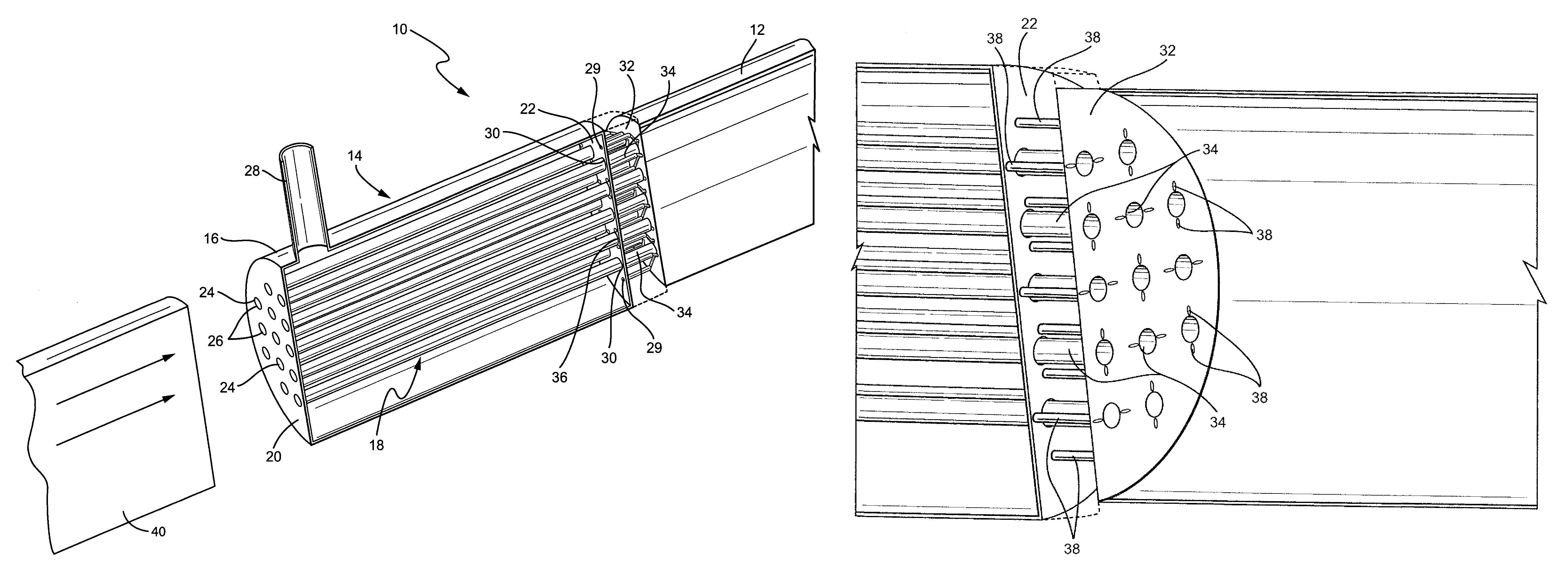
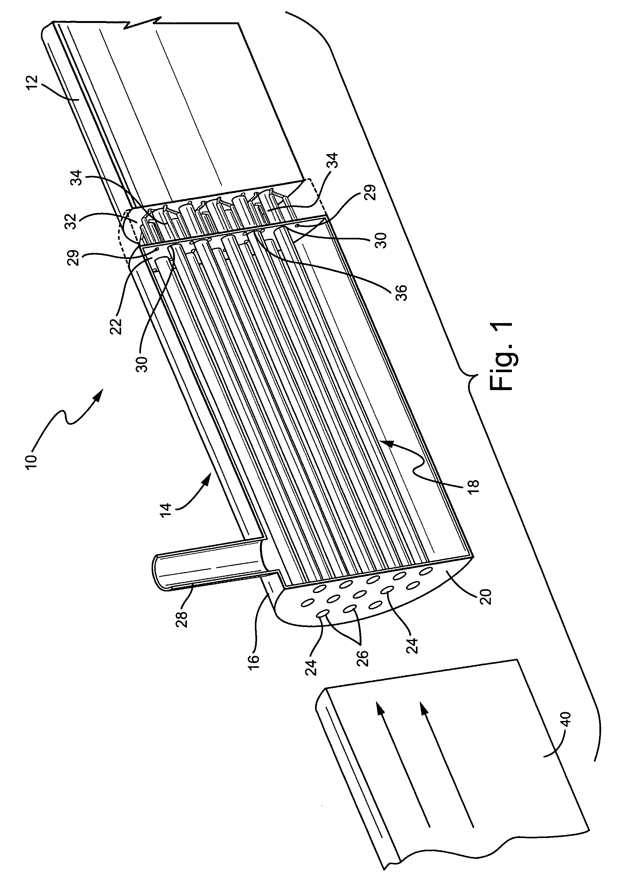
[0012]FIG. 1 is a partial cross-sectional, perspective view of one embodiment of the shell and tube lean direct injection combustion system 10 of the present invention. The shell and tube LDI combustion system 10 includes a combustor 12 and a shell and tube lean direct injector 14 that carries fuel and an oxidizer, such as air, to the combustor 12.

[0013]The shell and tube LDI 14 is comprised of a shell 16 and a bundle or plurality of tubes 18 positioned inside of the shell 16. In the embodiment of the LDI 14 shown in FIG. 1, the fuel is carried to the combustor 12 by the “shell side”16 of LDI 14, while the air is carried to the combustor 12 by the “tube side”18 of LDI 14. As an alternative, however, either side could contain fuel, air, or diluent, or any combination thereof.

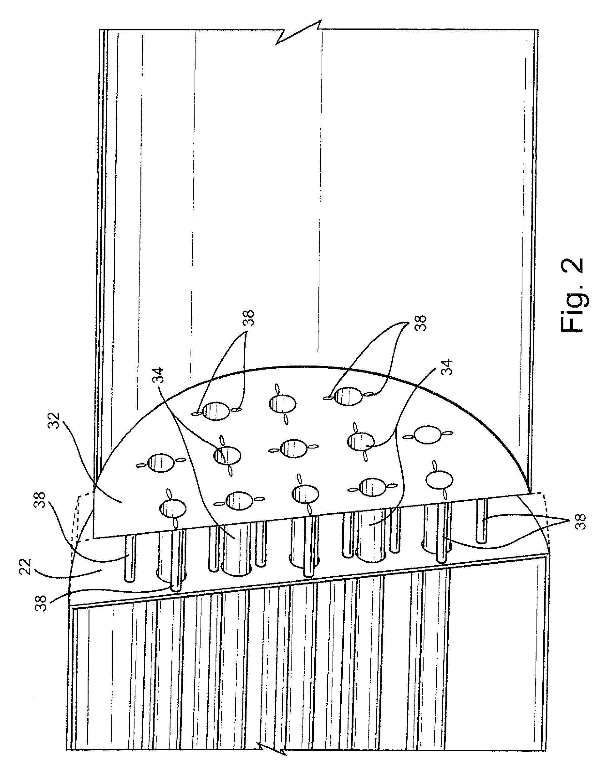
[0014]FIG. 2 is another partial cross-sectional, perspective view of the embodiment of the shell and tube lean direct injection combustion system 10 of FIG. 1 showing two sets of holes in an end plate of the comb...


PUM


Abstract

The present invention is directed to a lean direct injection (LDI) combustion system for a gas turbine using a shell and tube heat exchanger concept to construct a shell and tube lean direct injector (“LDI”) for the combustion system. One side of the LDI injector, either the shell side or the tube side, carries an oxidizer, such as air, to the combustor, while the other side of the LDI injector carries fuel to the combustor. Straight or angled holes drilled in an end plate of the combustor allow the fuel to enter the combustor and mix with air being injected into the combustor.

Description

[0001]The present invention is directed to gas turbines, and more particularly to a lean direct injection (LDI) combustion system using a shell and tube heat exchanger concept to carry fuel and air to the combustor.BACKGROUND OF THE INVENTION[0002]Most combustion processes have, in some way or another, a recirculating flow field. The recirculating flow field tends to stabilize the combustion reaction zone, but an unnecessarily large recirculation zone can result in high nitrogen oxide (NOx) emissions for combustion systems.[0003]Lean direct injection for combustion has been shown to have the potential to reduce NOx emissions. However, constructing a combustor to simply and uniformly inject many fuel and air streams presents a challenge. Non-premixed combustors typically use multiple fuel passages to inject fuel from a diffusion tip into air passing through an outer ring of the diffuser tip. This requires multiple diffuser tips with multiple separate air and fuel passages all mounted...

Claims


Application Information

Patent Timeline
Patent Type & Authority Patents(United States)
IPC IPC(8): F02C1/00F02G3/00
CPCF23R3/28
Inventor LACY, BENJAMINVARATHARAJAN, BALACHANDARZIMINSKY, WILLY STEVEKRAEMER, GILBERT O.BOARDMAN, GREGORY ALLENYILMAZ, ERTANMELTON, PATRICK
Owner GENERAL ELECTRIC CO
Why Eureka
Try Eureka