Injection head for a corrugator for the production of plastics pipes

a technology of injection head and plastic pipe, which is applied in the direction of dough shaping, application, manufacturing tools, etc., can solve the problems of time-consuming and laborious changes in injection head for the production of plastic pipe with a desired different diameter, affecting the manufacturing cost of known injection heads, and reducing production costs

Active Publication Date: 2011-10-25
UNICOR
View PDF26 Cites 2 Cited by
  • Summary
  • Abstract
  • Description
  • Claims
  • Application Information

AI Technical Summary

Benefits of technology

[0005]In the knowledge of these conditions, the invention is based on the object of providing an injection head of the type mentioned at the outset that is constructed in a comparatively simple manner and consists of relatively few individual parts, so that its production costs are reduced, the exchanging times for producing plastics pipes having differing diameters are comparatively short, and undesirable striation in the produced plastics pipe is reliably avoided.

Problems solved by technology

The nozzle body of known injection heads of the generic type therefore consists of a corresponding number of individual parts; this affects the manufacturing costs of known injection heads.
A further defect of known injection heads of the generic type consists in the fact that the at least one mouthpiece, which is attached to the nozzle body at the front, requires spacer rings for precise centering thereof, and that there is also a need, between the central body and the sleeve body of the mouthpiece that surrounds said central body, for centering pins which impede the flow of the melted plastics material, so that striation in the melted plastics material issuing from the output annular slot is often inevitable.
A very basic defect of known injection heads of the generic type consists in the fact that changing the injection head for the production of plastics pipes having a desired different diameter is time-consuming, i.e. the exchanging times are relatively long.

Method used


Image

  • Injection head for a corrugator for the production of plastics pipes
  • Injection head for a corrugator for the production of plastics pipes
  • Injection head for a corrugator for the production of plastics pipes

Examples


Embodiment Construction

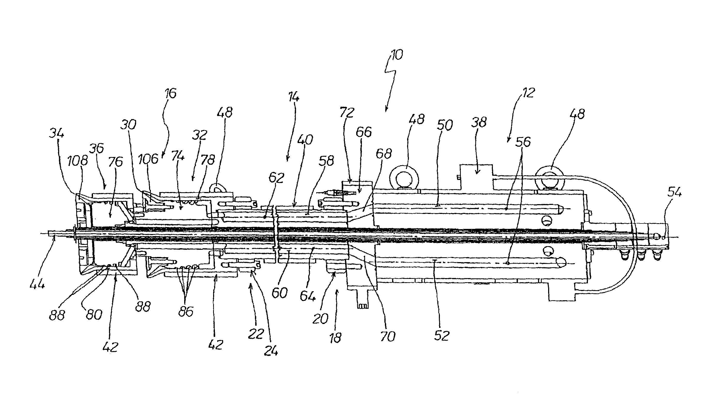
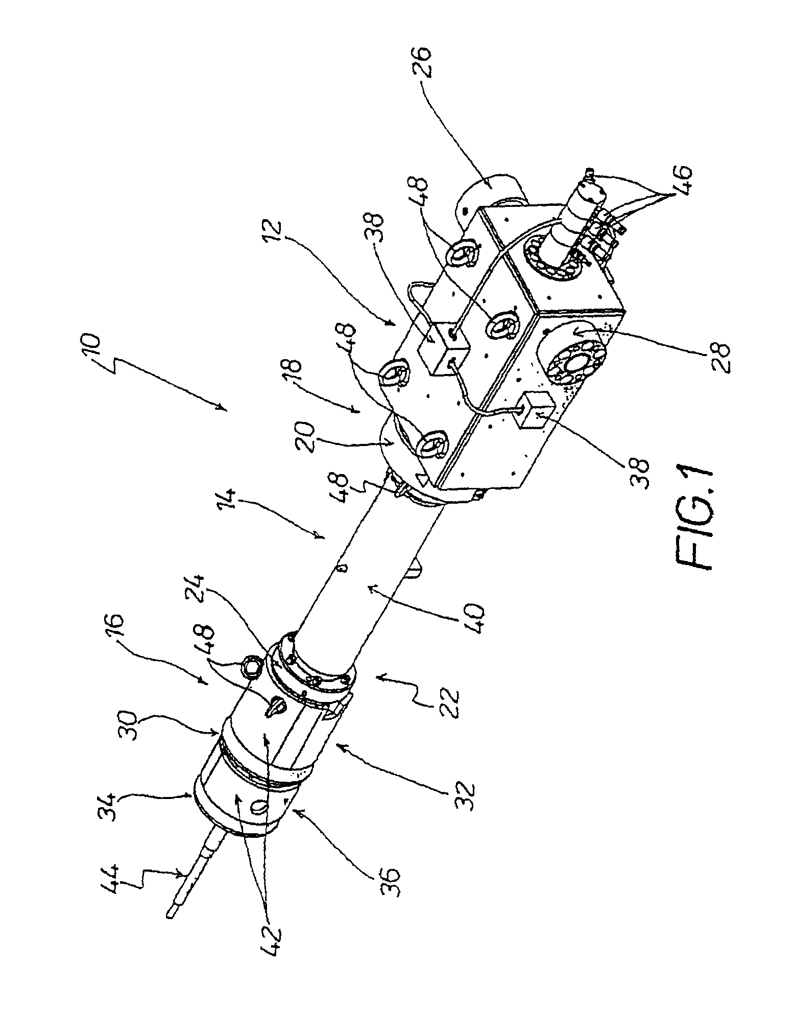
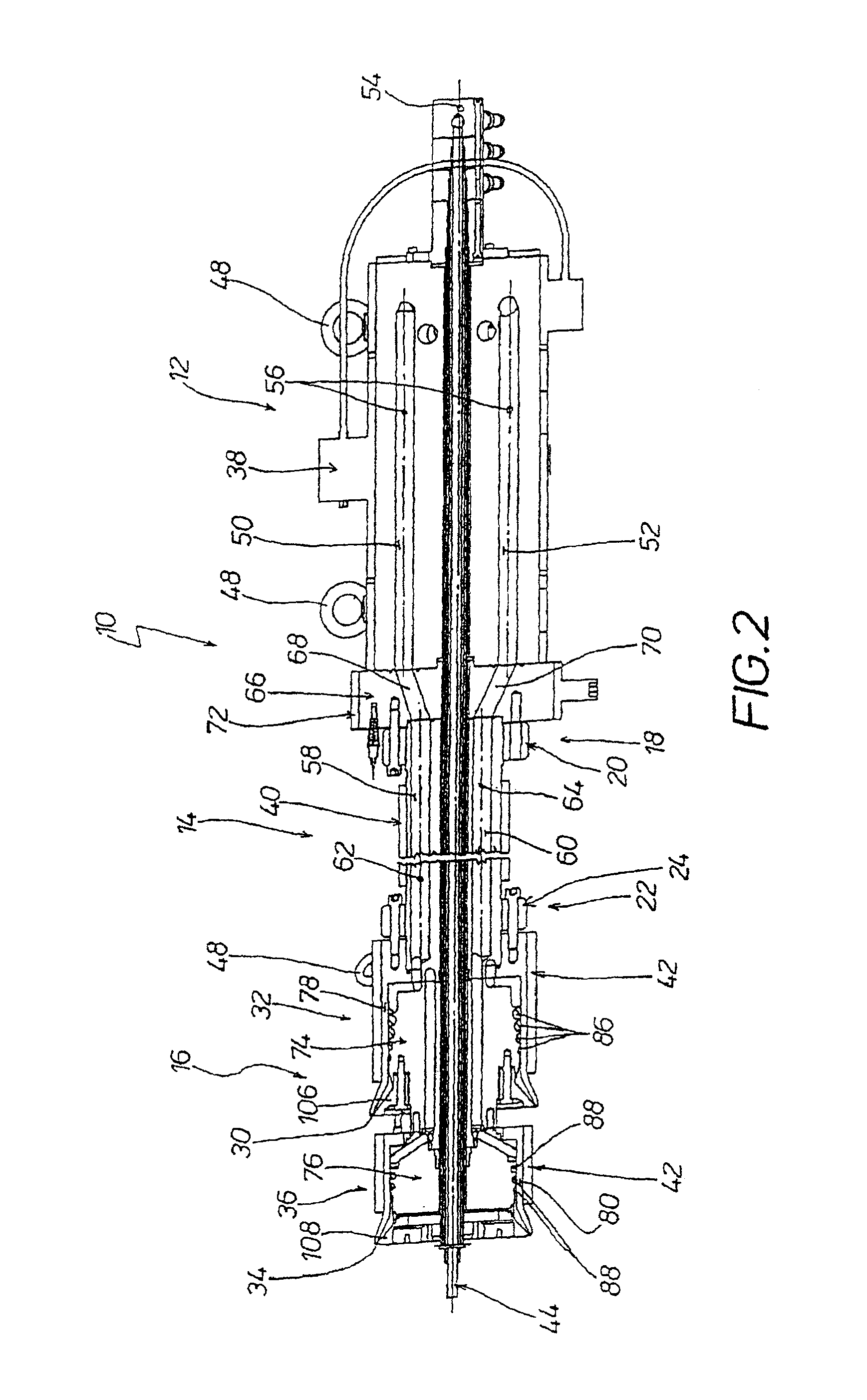
[0023]FIG. 1 is a perspective view of an embodiment of the injection head 10 for a corrugator for the production of plastics pipes having for example a smooth inner layer made of a first plastics material and a transversely corrugated outer layer which is integrally connected to said inner layer and is made of a second plastics material. The injection head 10 has a main head 12, a nozzle body 14 which is attached to the main head 12 so as to be in axial alignment and also a mouthpiece unit 16 which is attached to the nozzle body so as to be in axial alignment. For this purpose, the nozzle body 14 has on its back end portion 18 an annular flange 20 and on its front end portion 22 an annular flange 24.

[0024]The main head 12 of the injection head 10 has a first connection 26 for a first extruder and a second connection 28 for a second extruder by means of which the respective melted plastics material is introduced into the main head 12 and issues through the respectively associated out...


PUM

PropertyMeasurementUnit
dimensionsaaaaaaaaaa
diameteraaaaaaaaaa
diametersaaaaaaaaaa

Abstract

An injection head (10) is described for a corrugator which is intended for the production of plastics pipes. The injection head (10) has a main head (12), a nozzle body (14) and a mouthpiece means (16) with at least one mouthpiece (32, 36). The main head (12) is embodied with first channels (50, 52) and the nozzle body (14) is embodied with second channels (58, 60) which are flow-connected to the first channels (50, 52). The/each mouthpiece (32, 36) has a central body (74, 76) and a sleeve body, (78, 80) surrounding said central body. On its lateral surface (82, 84) facing the sleeve body (78, 80), the central body (74, 76) is embodied with wound plastics distributor grooves (86, 88) which are flow-connected by means of connecting portions (114, 120) to a concentric annular groove (112, 116) which is formed on the reverse surface (90, 92) of the central body (74, 76) and into which the second channels (58, 60) of the nozzle body (14) discharge.

Description

[0001]This application is the U.S. National Phase of, and Applicants claim priority from, International Application Number PCT / EP2007 / 007095 filed Aug. 10, 2007, which is incorporated herein by reference in its entirety.BACKGROUND OF THE INVENTION[0002]The invention relates to an injection head for a corrugator for the production of plastics pipes, with a main head having at least one connection for a plastics extruder, with a nozzle body which is attached to the main head so as to be in axial alignment and with at least one mouthpiece which is attached to the nozzle body so as to be in axial alignment and has an output annular slot for the corresponding plastics material, the at least one mouthpiece having a central body and a sleeve body surrounding said central body which determine the associated output annular slot.[0003]Injection heads of this type are known for example from U.S. Pat. No. 3,743,456, EP 0 208 055 A1, EP 0 230 055 A1 or DE 2 911 833 C2. They are used for example ...

Claims


Application Information

Patent Timeline
Patent Type & Authority Patents(United States)
IPC IPC(8): B29C47/20B29C48/09B29C48/13B29C48/30B29C48/32B29C48/335
CPCB29C47/862B29C47/126B29C47/0023B29C47/0033B29C47/06B29C47/0818B29L2023/22B29C47/86B29L2023/18B29C48/865B29C48/09B29C48/13B29C48/18B29C48/256B29C48/303B29C48/86
Inventor NEUBAUER, GERHARD
Owner UNICOR
Why Eureka
Try Eureka