
Rapid exchange balloon catheter and method for making same

a balloon catheter and balloon technology, applied in the field of rapid balloon catheters, can solve the problems of increasingimpede the procedure, and the catheter provides some challenges, and achieves the effects of reducing the risk of twisting and kinking, and reducing the risk of kinking

Active Publication Date: 2011-10-25
COOK MEDICAL TECH LLC
View PDF8 Cites 3 Cited by
  • Summary
  • Abstract
  • Description
  • Claims
  • Application Information

AI Technical Summary

Benefits of technology

The present invention is about a rapid exchange balloon catheter that has a smooth transition between a stiff metal body and a flexible plastics portion, which reduces the risk of kinking. The catheter has a reduced stiffness transitional region in the metal body, which avoids the need for a separate reinforcing member. The stiffness of the metal body at the transitional region is reduced compared to the rest of the metal body by about half. The catheter can be made from stainless steel or a shape memory nickel-titanium alloy, which provides increased pushability and torquability in the narrow bends and curvature of the vascular system of a patient. The transitional region can be created by weakenings or heat treatment. The invention provides a consistent and cost-effective method for making a rapid exchange catheter with improved kink resistance.

Problems solved by technology

The guide wire must hence have a length of about twice the length of the catheter, e.g. 3 m in total, which greatly impedes the procedure.
However the rapid exchange catheter provides some challenges, especially with regard to resistance to kinking of the catheter.
An abrupt change of properties between the shaft portion and the distal portion however increases the risk of twist and kinking.
Although this construction has some effect on the kink resistance, it is somewhat difficult to manufacture and hence expensive.
The reinforcing member must be stocked and handled inevitably raising the cost, and further there is an increased risk of leakage from the catheter due to the extra joints, thereby raising the costs to skilled personnel and quality check.

Method used


Image

  • Rapid exchange balloon catheter and method for making same
  • Rapid exchange balloon catheter and method for making same
  • Rapid exchange balloon catheter and method for making same

Examples


Embodiment Construction

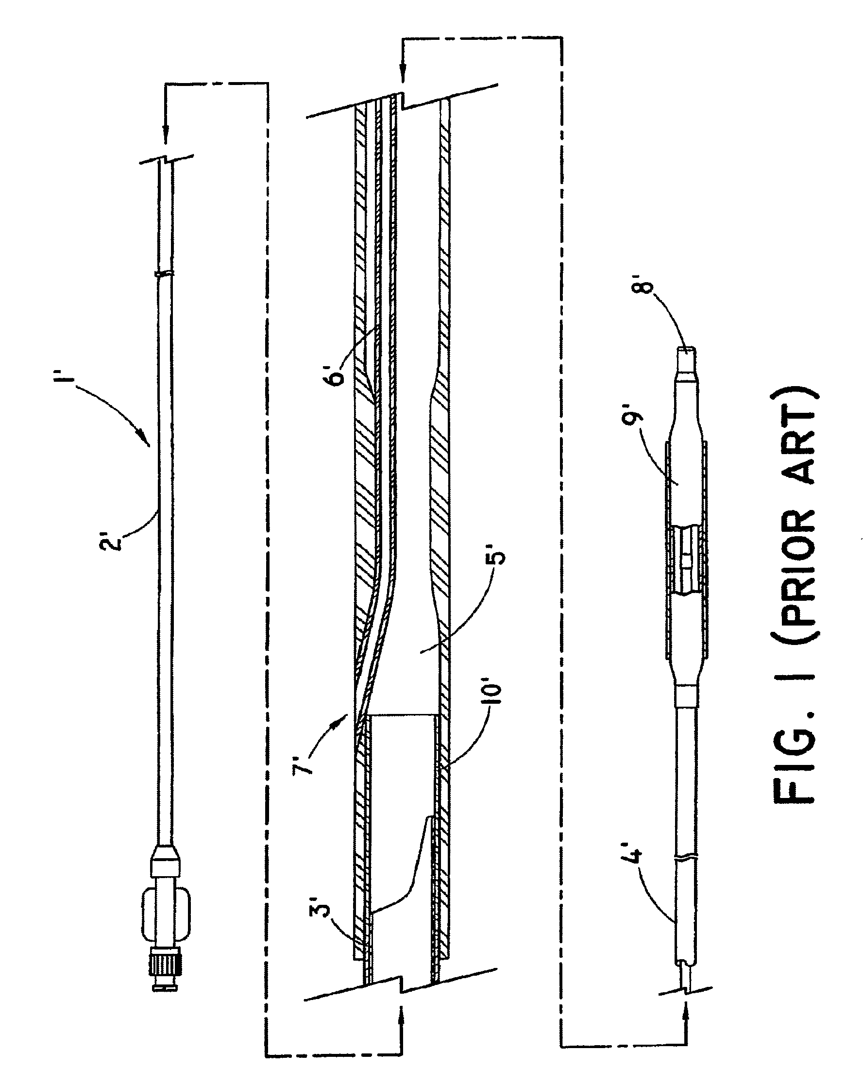
[0022]A prior art rapid exchange catheter according to U.S. Pat. No. 6,746,423 as discussed above is seen in FIG. 1. This prior art catheter 1′ comprises a tubular metal shaft body 2′ extending from the proximal end along a majority of the total length and having an inflation lumen 3′ arranged therein. The catheter 1′ further comprises a plastics distal end portion 41 bonded to the metal body in extension thereof. The distal end portion 4′ is provided with an inflation lumen 5′ and a guide wire lumen 6′, said guide wire lumen 6′ extending from a proximal side port 7′ to a distal end opening 8′. The catheter 1′ further comprises a balloon 9′ arranged at the distal end of the catheter. This prior art catheter 1′ further incorporates a reinforcing member 10′ in form of a tube bridging the region of junction between the metal body 2′ and the plastics distal end portion 4′.

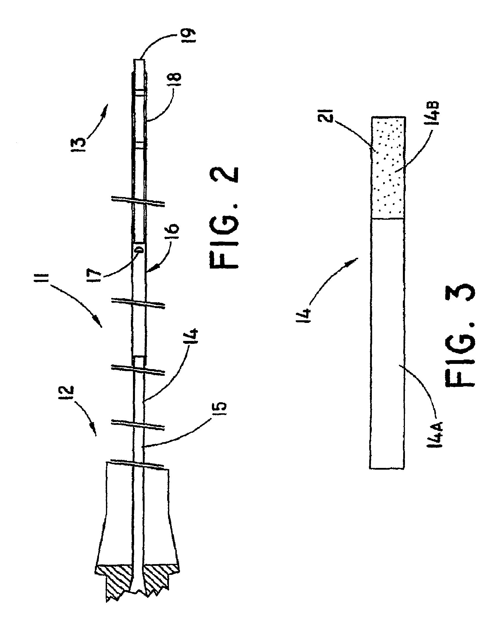
[0023]In FIG. 2 is shown a catheter according to the invention. This figure is somewhat distorted for illustration p...


PUM

PropertyMeasurementUnit
lengthaaaaaaaaaa
lengthaaaaaaaaaa
lengthaaaaaaaaaa

Abstract

A rapid exchange balloon catheter having a proximal end and a distal end, said catheter comprising: a tubular metal shaft body extending from the proximal end along a majority of the total length and having an inflation lumen arranged therein, a plastics distal end portion bonded to the metal body in extension thereof, said distal end portion being provided with an inflation lumen in communication with a balloon, and a guide wire lumen, said guide wire lumen extending from a proximal side port to a distal end opening. To reduce the resistance to kinking, the metal body comprises a transitional region having reduced stiffness at the position of bonding to the plastics distal end portion compared to a more proximal position along the metal body.

Description

[0001]This application is a continuation of International Application No. PCT / US2006 / 044495, filed Nov. 16, 2006, which claims the benefit of U.S. Provisional Application Ser. No. 60 / 737,124, filed Nov. 16, 2005. These references are incorporated herein in their entirety.TECHNICAL FIELD[0002]The present invention relates to a rapid exchange balloon catheter.BACKGROUND OF THE INVENTION[0003]Catheters have found widespread use in medical procedures, such as percutaneous transluminal coronary angioplasty (PTCA) or for delivery of stents. Most catheters are guided to the application site by sliding the catheter along a guide wire, which has been carefully advanced and arranged within the patient. During advancement of the catheter along the guide wire, it is important to keep the guide wire steady. Ordinary catheters are guided to the application site in a patient by sliding the catheter along a guide wire extending all the way through a lumen of the catheter from the proximal end to th...

Claims


Application Information

Patent Timeline
Patent Type & Authority Patents(United States)
IPC IPC(8): A61M29/00A61F2/958
CPCA61M25/0054A61M25/1036Y10T156/10A61M2025/0183
Inventor HANSEN, PALLE M.AGGERHOLM, STEEN
Owner COOK MEDICAL TECH LLC
Learn More