Internal bone transport

a bone grafting and internal bone technology, applied in the field of orthopedic devices, can solve the problems of increased blood loss, pain, surgical scarring, and difficulty or inability to obtain the optimal volume of autogenous bone, and achieve the effect of reducing the volume of fluid

Active Publication Date: 2011-10-25
CONWAY JANET
View PDF8 Cites 97 Cited by
  • Summary
  • Abstract
  • Description
  • Claims
  • Application Information

AI Technical Summary

Benefits of technology

[0014]According to an embodiment of the present invention, the internal bone transport device has an external rod of substantially fixed length (also referred to as “substantially fixed length rod”) with two ends, each of which may be coupled, attached, or affixed to a different bone. The internal bone transport has at least one moveable member that is capable of moving along the internal rod. The moveable member is coupled to a bone and moved along the length of the external rod by an external magnet that rotates a magnetic material housed within the external rod. The moveable member has a projecting member for coupling the middle bone to the moveable member. An internal rod (also referred to as “longitudinally rotatable rod”), which may be threaded, is housed within the external rod and may optionally be coupled with a gearbox. The gearbox is coupled with the magnetic material such that when an external magnetic field is created, the magnetic material is rotated. The rotation of the magnetic material in turn causes the gearbox to rotate the coupled internal rod. The rotation of the internal rod causes the moveable member to move lengthwise along the internal rod and substantially parallel to the external rod. Rotation of the internal rod does not cause the moveable member to rotate, but rather causes the moveable member to move in a substantially lengthwise direction within the external rod. The internal bone transport permits bidirectional movement of a bone lengthwise along the external rod.
[0015]According to an embodiment of the invention, the internal bone transport device has a hydraulic or fluid actuator in combination with a compression or torsional spring instead of a magnetic actuator. As in the previously described embodiments, the internal bone transport device of the fluid actuator embodiment has a substantially fixed length rod with two ends; each end may be coupled, attached, or affixed to a different bone. The internal bone transport has at least one moveable member that is capable of moving along the internal rod. The moveable member is coupled to a bone and moved along the length of the substantially fixed length rod. One end of a compression spring is attached, or affixed to one end of the substantially fixed length rod, while the other end of the compression spring is attached, or affixed to the moveable member. A sealed variable volume fluid container such as, without limitation, a sealed silicone bladder is positioned between the other end of the substantially fixed length rod and the moveable member. A flexible conduit has one end fluidly coupled to the fluid container, while the other end is fluidly coupled to a one-way valve. The fluid container and flexible conduit are filled with a fluid compatible with the body such as saline. An actuator is positioned outside the device and may be positioned outside the body operable to control the one-way valve. The actuator is preferably a remote control device such as a magnetic, electromagnetic, radio frequency, and mixtures thereof controlled device. Movement of the moveable member is caused by the actuator opening the one-way valve to allow fluid to escape the variable volume fluid container and flexible conduit. This decreases the volume of fluid in the fluid container, thus, allowing the compression spring to act against the moveable member from the other side to cause the moveable member to move in a substantially lengthwise direction within the external rod.
[0016]According to an embodiment of the invention, two moveable members are used to transport a pair of bone segments towards one another. The internal bone transport device has a variable volume fluid container between the pair of moveable members. The device further includes a pair of compression springs such that each spring is attached, or affixed, at one end to a moveable member and at the other end to one end of the external rod. Upon actuation by an actuator, fluid is released from the variable-volume fluid container thus, allowing the compression springs to expand. The expansion of the compression springs transports each moveable member along the internal rods towards the other moveable member. Thus, a pair of bone segments is able to be transported at the same time.

Problems solved by technology

Autogenous bone grafting has the disadvantage of donor site morbidity including pain, increased blood loss, and surgical scarring.
Furthermore, in the case of large defects it may be difficult or impossible to obtain an optimal volume of autogenous bone.
While allografting eliminates the problem of adequate quantity, the incidence of complications such as infection, fracture, and non-union is increased.
However, transfixing wires used in this technique can cause significant complications including wire site infection, pain, and restricted joint motion due to the transfixation of tendons and muscles.
Such a mechanism can cause infection and discomfort at the site where the cable penetrates the soft tissue.
There are several internal lengthening devices that have been patented, but none of the devices address the problem of transfixing a moving middle segment of bone along the length of a rod without changing the overall length of the rod.
However, none of them allow a third middle segment of bone to move in a bidirectional mode upon rotation of an external magnet.
The pins, wires, cables, and other structures (herein collectively “pins”) that penetrate the soft tissue in the prior art are sources of infection.
This causes problems with joint contractures secondary to the transfixing of these soft tissues.
The pins dragging through the skin also causes large scar tracts to be formed which are unsightly and often require surgical excision.

Method used


Image

  • Internal bone transport
  • Internal bone transport
  • Internal bone transport

Examples


Embodiment Construction

[0029]Reference will now be made in detail to embodiments of the invention, examples of which are illustrated in the accompanying drawings. While the invention will be described in conjunction with the embodiments, it will be understood that they are not intended to limit the invention to those embodiments. On the contrary, the invention is intended to cover alternatives, modifications, and equivalents, which may be included within the spirit and scope of the invention as defined by the appended claims.

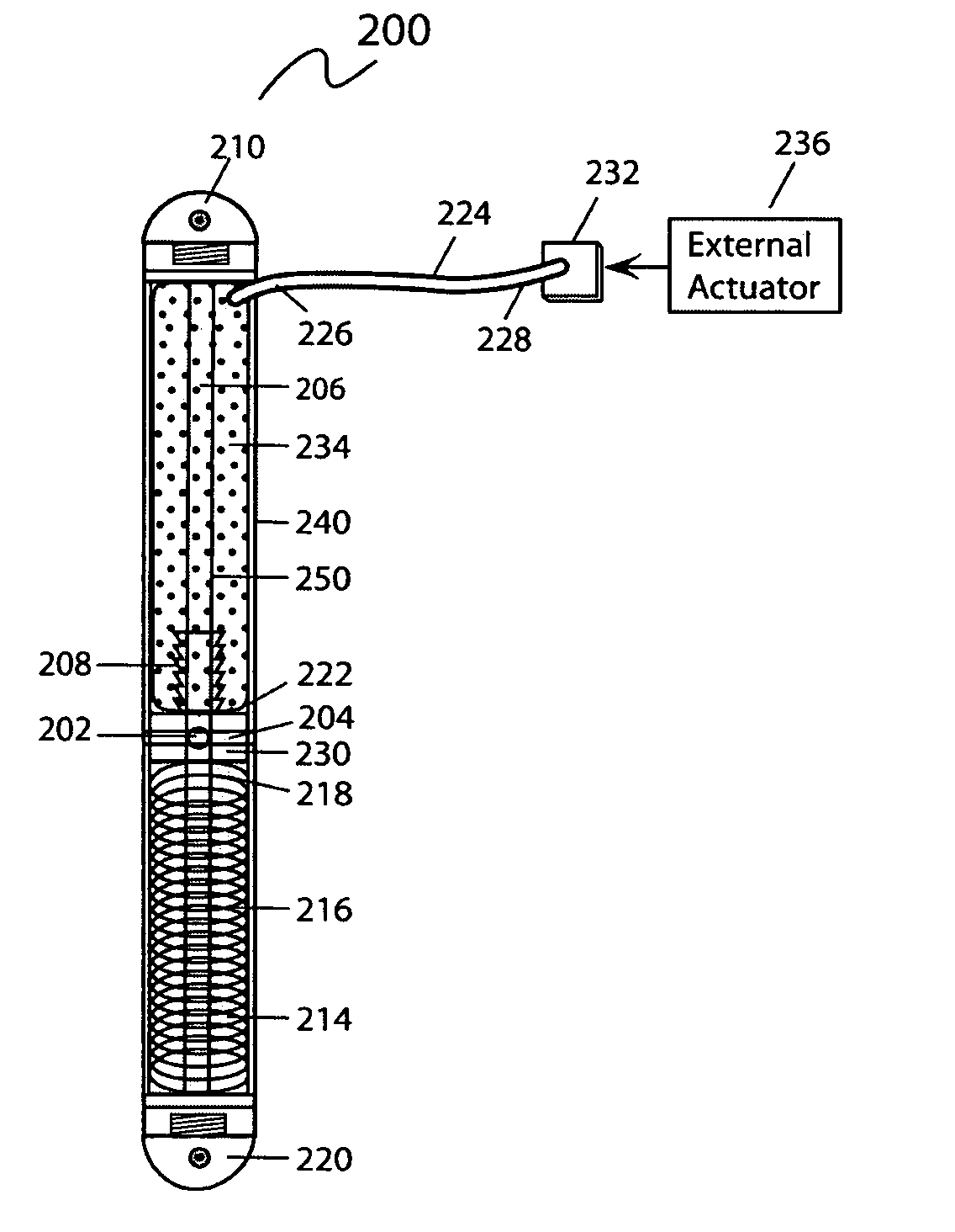
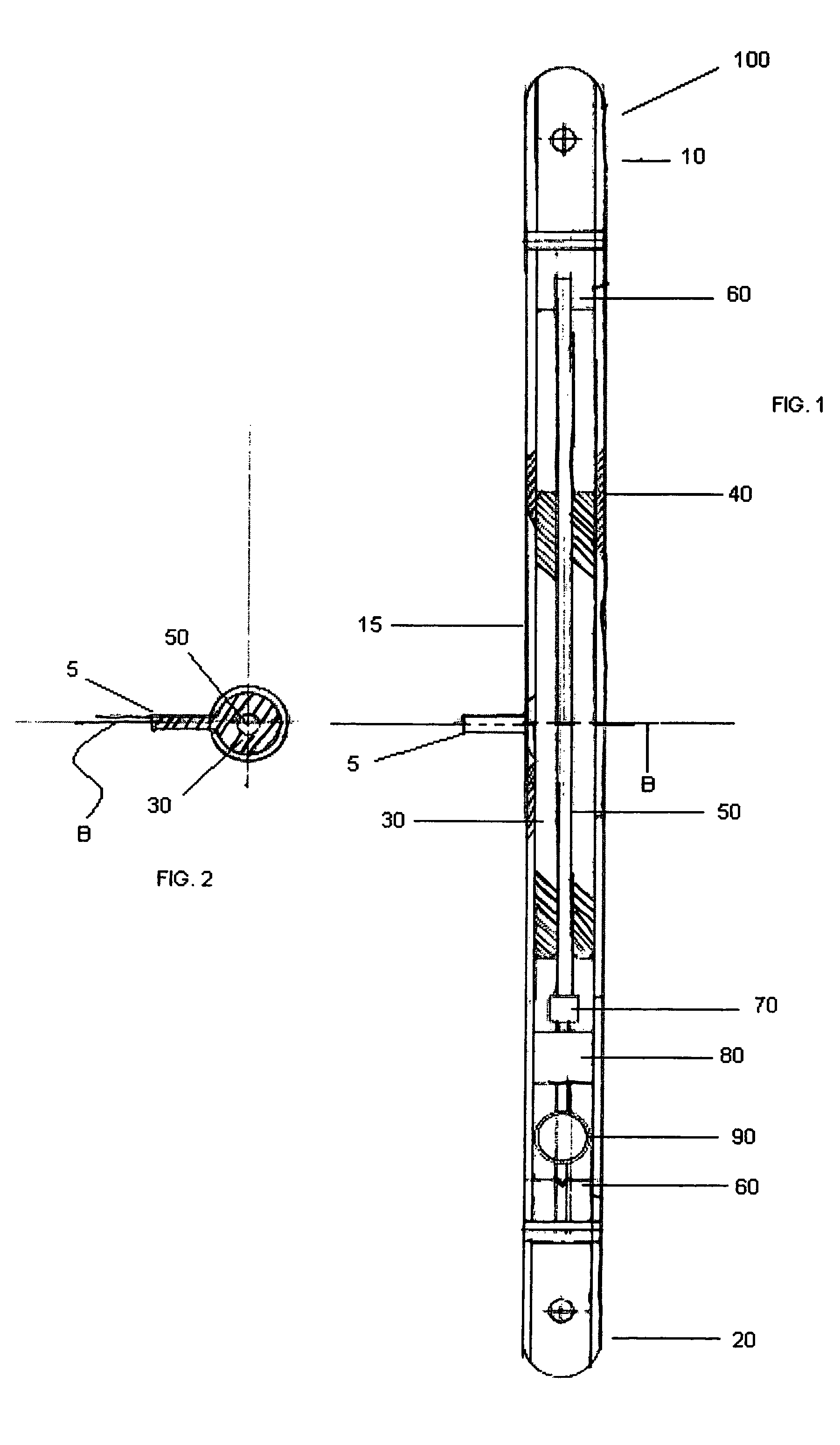
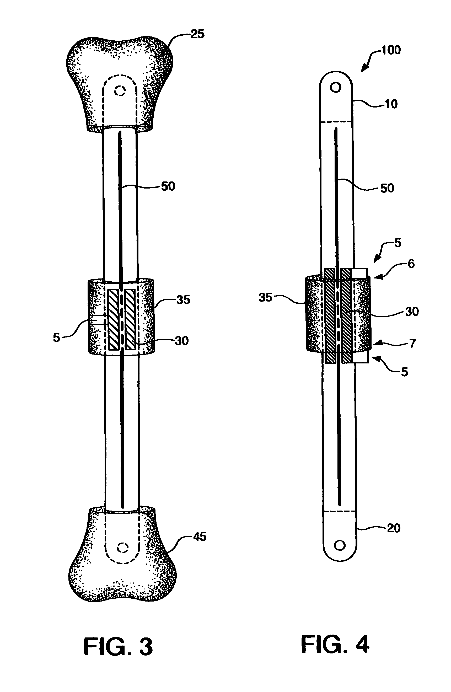
[0030]According to an embodiment illustrated in FIG. 1, the internal bone transport (100) has an external rod or tube (herein collectively “external rod”) (40) having a first end (10) and second end (20). The first end (10) and second end (20) are capable of being coupled with a bone. The first end (10) and second end (20) may be coupled with a bone by methods known in the art, including but not limited to screws, pins, cement, and / or glue. Preferably, the first end (10) and the secon...


PUM


Abstract

An internal bone transport device and method for lengthen bone that, once surgically implanted will allow for a segment of bone to be transported along the length of the rod without changing the overall length of the rod. The segment from one bone end is transported to the other in a controlled fashion allowing for complete control of the rate of bone transport and adjusting this rate to the quality of the bone formation. The segment is moved either by the application of an externally applied magnetic force or by a fluid actuator in combination with a compression spring. It applies to patients in whom a segment of bone has been removed. This fully internal bone transport allows the bone transport to occur without any external fixation, thus eliminating the problems associated with pin tract infections and pain from the pins cutting through the soft tissue.

Description

CROSS-REFERENCE TO RELATED U.S. APPLICATION[0001]This application is a continuation-in-part of U.S. patent application Ser. No. 11 / 593,999, filed on Nov. 6, 2006, the contents of which are hereby incorporated by reference.TECHNICAL FIELD OF THE INVENTION[0002]Generally, the present invention relates to an orthopedic device. More particularly, the present invention relates to an apparatus and methods for moving and lengthening bone.BACKGROUND OF THE INVENTION[0003]There are many means of stabilizing, moving, and lengthening bone. The need arises to stabilize, move and / or lengthen (collectively “lengthen”) bone in a variety of situations, for example, to increase stature, even the length of a pair of limbs, and when a section of bone is removed following illness or trauma. Intercalary defects in long bones may occur as a result of trauma or after the resection of tumors or infection. With appropriate mechanical fixation, these defects may be managed by autogenous bone grafting, segmen...

Claims


Application Information

Patent Timeline
Patent Type & Authority Patents(United States)
IPC IPC(8): A61B17/56A61B17/58A61F2/00A61F2/30A61B17/60
CPCA61B17/7216A61B17/7291A61B2017/00004A61B2017/00137A61B2017/00212
Inventor CONWAY, JANET
Owner CONWAY JANET
Why Eureka
Try Eureka