Sensor product for electric field sensing

a technology of sensor products and electric fields, applied in the direction of electric digital data processing, instruments, electrical apparatus, etc., can solve the problems of limited scalability for large areas, poor application for outdoor or harsh environments, and the generality of user interface devices that are relatively fragile and expensive. , to achieve the effect of high electrical conductivity

Active Publication Date: 2011-10-25
ELSI TECHNOLOGIES OY
View PDF19 Cites 19 Cited by
  • Summary
  • Abstract
  • Description
  • Claims
  • Application Information

AI Technical Summary

Benefits of technology

[0010]A specific object is to provide a sensor product that comprises an array or matrix of electrically conductive areas and conductors on a flexible substrate, and a method for manufacturing it. The electrically conductive areas form sensor elements. In this arrangement the sensed area is scalable by increasing the number of the electrically conductive areas. It is also possible to increase the area of the electrically conductive areas and the distances between them at the expense of resolution.
[0012]The present invention also provides conductors between the electrically conductive areas and the output and protective layers if desired. The conductors may be made using the same material and manufacturing process as the electrodes. However, in order to maximize the cost efficiency in some cases it might be advantageous to use a different material and process for electrodes and conductors. The manufacturing process steps of the present invention also enable utilization of a continuous roll-to-roll process.
[0015]The sensor product of the invention can be used, for example, for user-computer interfaces and for sensing bodies. The touch-free operation, scalability, flexibility, robustness, and low-cost manufacturing enable a large variety of applications. In connection with the user-computer interfaces, the sensor product can be a substitute for a keyboard, a mouse, a touch pad, or a touch screen, or the sensor product can be used in parallel with them. The sensor product can be used as smart blackboards, whiteboards, or flipcharts. Further, the sensor product can be used at info kiosks, cash machines, and in industrial control panels. The sensor product can be hidden In / on / behind / under construction elements, for example walls, panels, boards, tables, displays, windows, or posters.

Problems solved by technology

Most of the user interface devices are typically relatively fragile and expensive, have limited scalability for large areas, and are poorly applicable for use outdoors or in harsh environments.

Method used


Image

  • Sensor product for electric field sensing
  • Sensor product for electric field sensing
  • Sensor product for electric field sensing

Examples


example 1

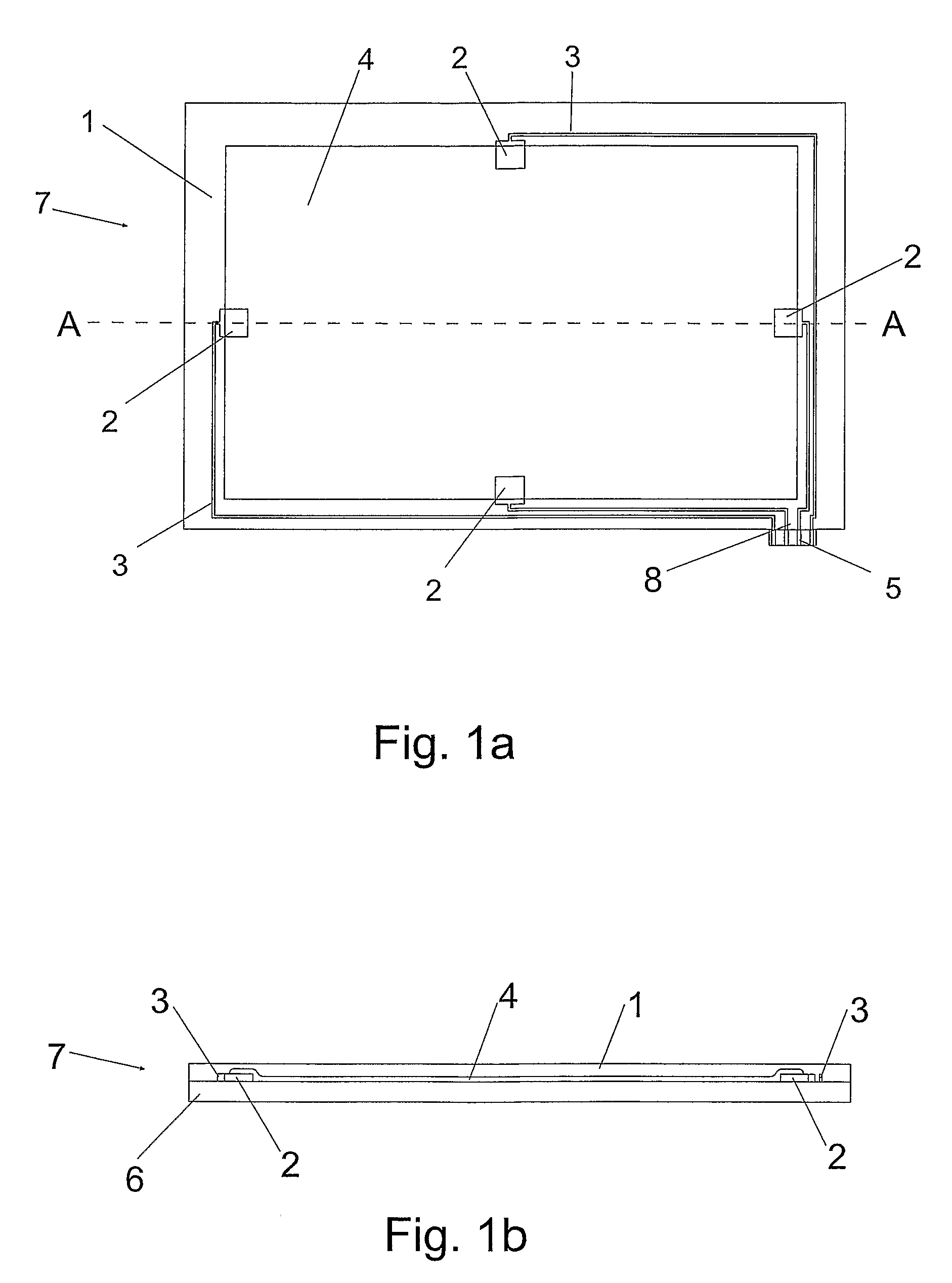
[0044]A sensor product according to FIG. 1 was manufactured. The electrodes and conductors of the sensor product are of aluminium, and the resistive sheet is a printed area. The electrically conductive element of the printing ink is carbon.

[0045]The manufacturing process of the sensor product comprises:[0046]1. The conductors and electrodes can be made by any known aluminum etching technique by using the following process:[0047]a. Resist printing i.e. printing a conductor / s and an electrode pattern / s to a Al / PET laminate (e.g. PET / adhesive / aluminium) with a resist ink (e.g. Coates XV1000-2).[0048]b. Etching of the Al / PET laminate[0049]2. A resistive sheet is printed by using conducting carbon ink (e.g. Dupont 7102) on top of the etched PET—film. The conductivity of the carbon ink can be adjusted to the desired level by using dielectric paste (e.g. Dupont 3571). According to the research results, optimal resistance with a 141×225 mm size sheet is 0.9-1.1 MΩ, measured between two elec...

example 2

[0057]A sensor product according to FIG. 1 was manufactured. Electrodes and conductors of the sensor product are of copper, and the resistive sheet is a printed area. The electrically conductive element of the printing ink is carbon.

[0058]Manufacturing steps:[0059]1. Conductors and electrodes can be made by any known copper etching technique by using the following process steps:[0060]a. Resist printing i.e. printing conductor and electrode pattern on the copper PET laminate with resist ink (e.g. Coates XV1000-2).[0061]b. Etching of copper laminate (e.g. PET—adhesive—copper).[0062]2. Resistive area (the resistive sheet) is printed by using electrically conductive carbon ink (e.g. Dupont 7102) on top of the etched PET—film. The conductivity of the carbon ink can be adjusted to the desired level by using a dielectric paste (e.g. Dupont 3571). According to the research results, optimal resistance with a 141×225 mm size sheet is 0.9-1.1 MΩ, measured between two electrodes at opposite sid...

example 3

[0071]A sensor product according to FIG. 1 was manufactured. Electrodes and conductors of the sensor product are printed with a silver ink, and the resistive sheet is a printed area. The electrically conductive element of the printing ink is carbon.

Manufacturing Steps:

[0072]1. Conductors and electrodes are printed with conducting silver ink on the substrate (e.g. PET film)[0073]2. A resistive sheet area is printed by using conducting carbon ink (e.g. Dupont 7102) on top of the etched PET—film. Conductivity of the carbon ink can be adjusted to the desired level by using dielectric paste (e.g. Dupont 3571). According to the research results, optimal resistance with a 141×225 mm size sheet is 0.9-1.1 MΩ, measured between two electrodes at opposite sides of the sheet in the length direction. The resistance may vary from 10 kΩ to 100 MΩ depending on the size of the sheet and the application). The carbon printed area overlaps with the silver electrodes.[0074]3. Lamination of a protective ...


PUM


Abstract

A sensor product for electric field sensing. The sensor includes a substrate, at least one electrically conductive area on the surface of the substrate, an output, and at least one conductor between the at least one electrically conductive area and the output. Also a sensor product web.

Description

CROSS-REFERENCE TO RELATED APPLICATIONS[0001]This application claims priority to U.S. provisional patent application 60 / 585,711 filed 6 Jul. 2004 and is the national phase under 35 U.S.C. §371 of PCT / FI2005 / 000312 filed 5 Jul. 2005.FIELD OF INVENTION[0002]The present invention relates to a sensor product. The sensor product can be used in computer user interfaces, occupant or passenger monitoring systems, e.g. in keyboards, smart air bag systems, and floor constructions.BACKGROUND[0003]Electric field sensing refers to a method for determining positions, movements and geometries of objects on the basis of disturbances which they cause to a surrounding electric field.[0004]Most of the pioneering work in electric field sensing can be attributed to nature. Electric fields are, used by various aquatic animals for sensing their environment, especially in the dark, muddy waters where light is scarce (Bastian J., Electrosensory Organism, Physics Today, pages 30-37, February 1994).[0005]Prof...

Claims


Application Information

Patent Timeline
Patent Type & Authority Patents(United States)
IPC IPC(8): G01R29/12H03M11/00G06F3/041
CPCG01R19/145G01R27/2617G06F3/044G06F2203/04103G06F2203/04111G06F3/0445
Inventor JOUTSENOJA, TIMOKYYNY, KARI
Owner ELSI TECHNOLOGIES OY
Why Eureka
Try Eureka