RF array coil system and method for magnetic resonance imaging

a magnetic resonance imaging and array coil technology, applied in the field of magnetic resonance imaging (mri) systems, can solve the problems of large coils, no useful information, enlarged bird cage heads, etc., and achieve the effect of reducing the signal-to-noise ratio (snr or s/n) and reducing the size of the coils

Active Publication Date: 2011-10-25
GENERAL ELECTRIC CO
View PDF5 Cites 32 Cited by
  • Summary
  • Abstract
  • Description
  • Claims
  • Application Information

AI Technical Summary

Problems solved by technology

The magnetic moments point in the direction of the main magnetic field in a steady state, but produce no useful information if these magnetic moments are not disturbed by any excitation.
A large coil, however, produces lower signal-to-noise ratio (SNR or S / N) if it is also used for reception, mainly because of its greater distance from the signal-generating tissues being imaged.
The enlargement of the birdcage head coil reduces the performance (e.g., SNR) of the head section of the asymmetric birdcage coil as compared to a conventional birdcage head coil.
The anterior neck-torso coil section also is located a substantial distance from a patient's chest and the shape is often not optimized to fit the human neck-chest contour.
This limits the coverage of the asymmetric birdcage coil, for example, to only the head and neck and not to the aortic arch.
Thus, this neurovascular coil also results in lower performance, for example, lower SNR for the head imaging as compared to a conventional quadrature head coil and imaging non-uniformity of the chest region due to the quick SNR drop-off in this region.
The coverage of this two-channel quadrature volume array coil is limited to the head and neck and cannot image, for example, the aortic arch.
Further, the decoupling of the multiple modes (i.e., multiple NMR frequencies) birdcage type anterior and posterior neck-torso coils from the multiple modes birdcage head coil is complex in design.
The performance of the head section of these neurovascular coils is lower than conventional standard birdcage head coils because of the design limitations.
These coil arrangements again have design limitations.
These known coils not only have design limitations, but when used in SENSE operations, imaging in both the left-right (LR) and anterior-posterior (AP) directions is not possible in the head region.
The complex sensitivity of the head coil elements does not allow for SENSE imaging to be performed.
However, signal drop-off may be experienced between the head and torso regions, which causes shading at the neck region.
This further results in shading problems at the neck region.
Additionally, this arrangement does not facilitate parallel imaging in the superior-inferior direction in the head region and in the torso region.

Method used


Image

  • RF array coil system and method for magnetic resonance imaging
  • RF array coil system and method for magnetic resonance imaging
  • RF array coil system and method for magnetic resonance imaging

Examples


Embodiment Construction

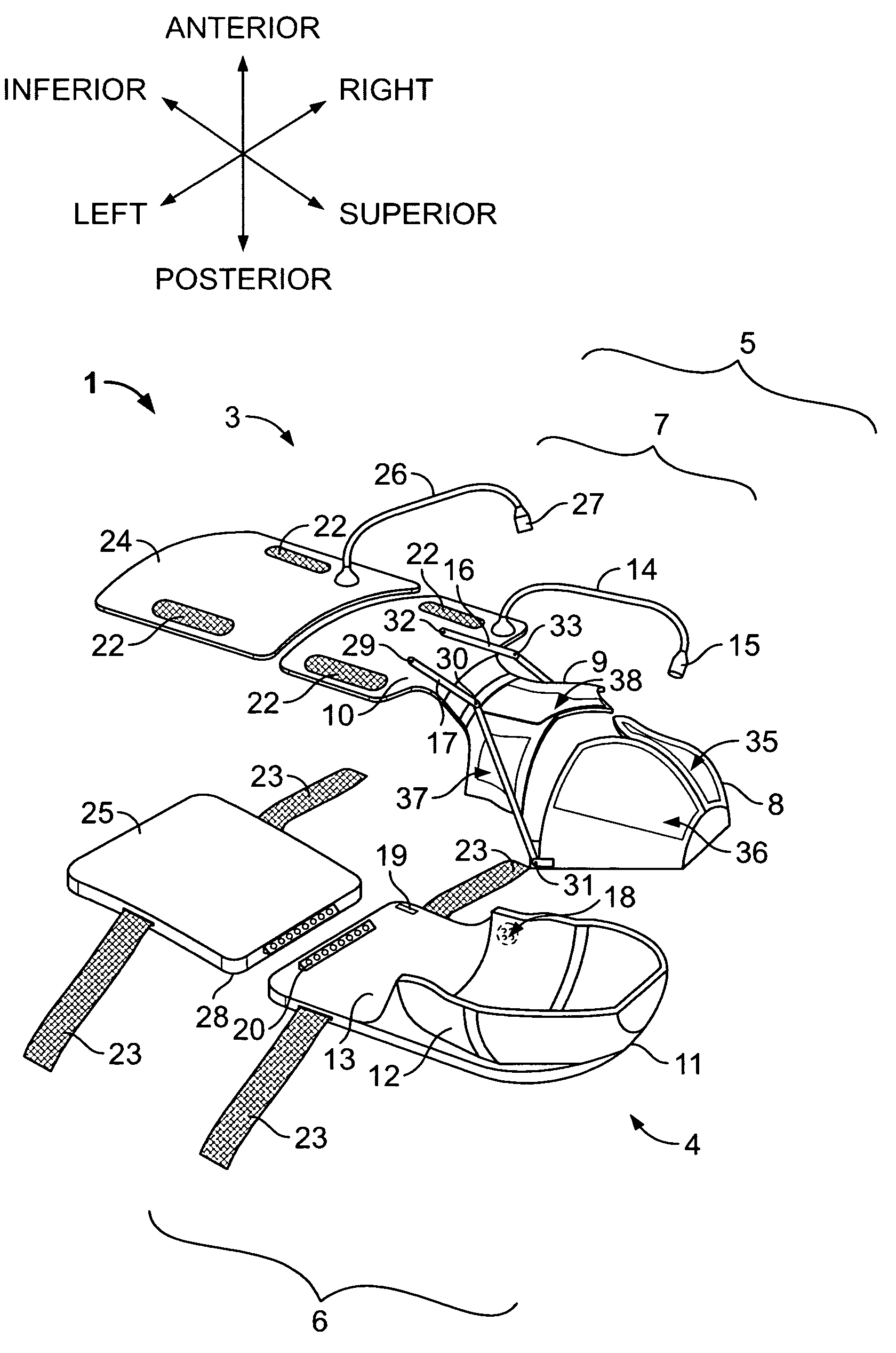
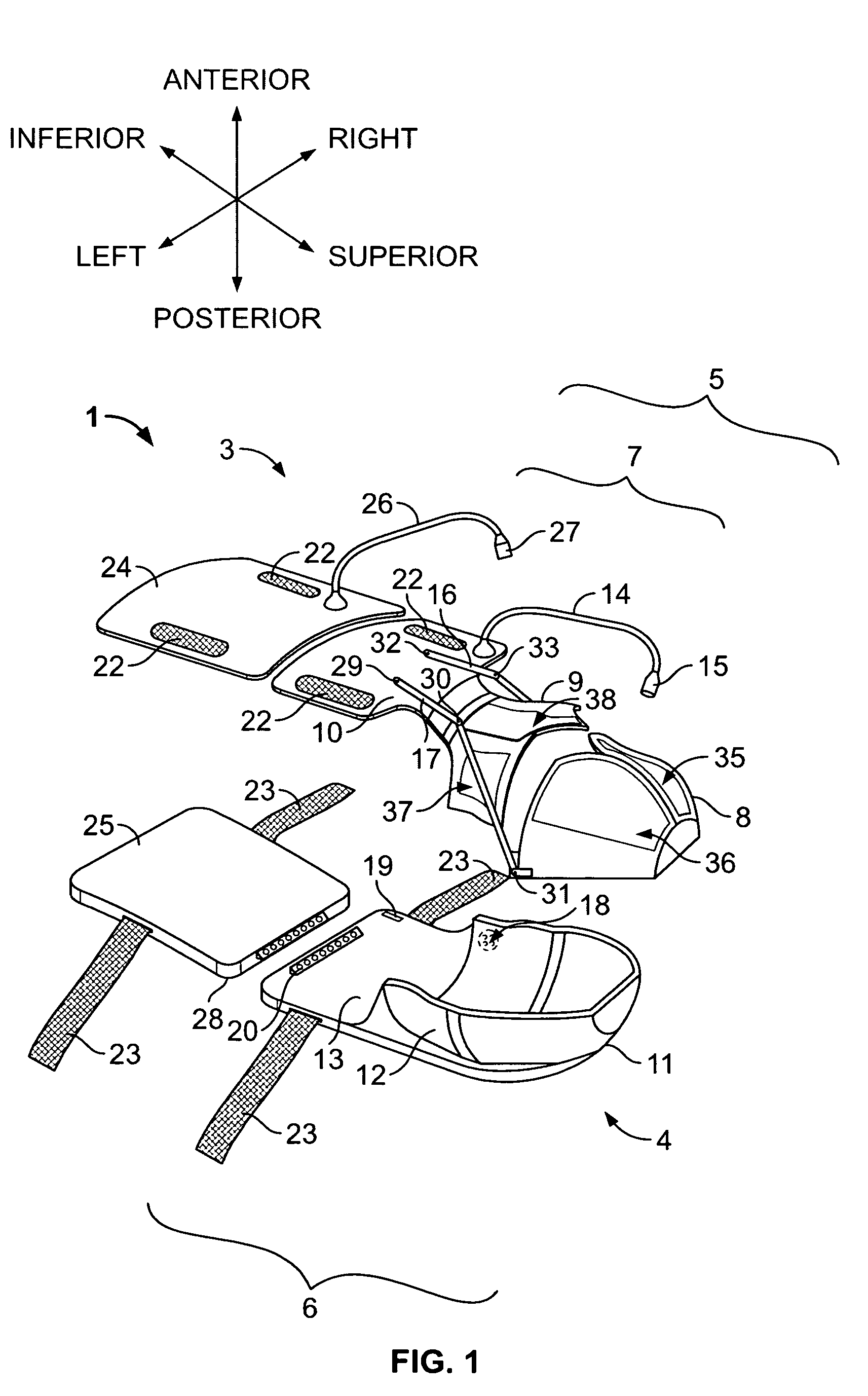
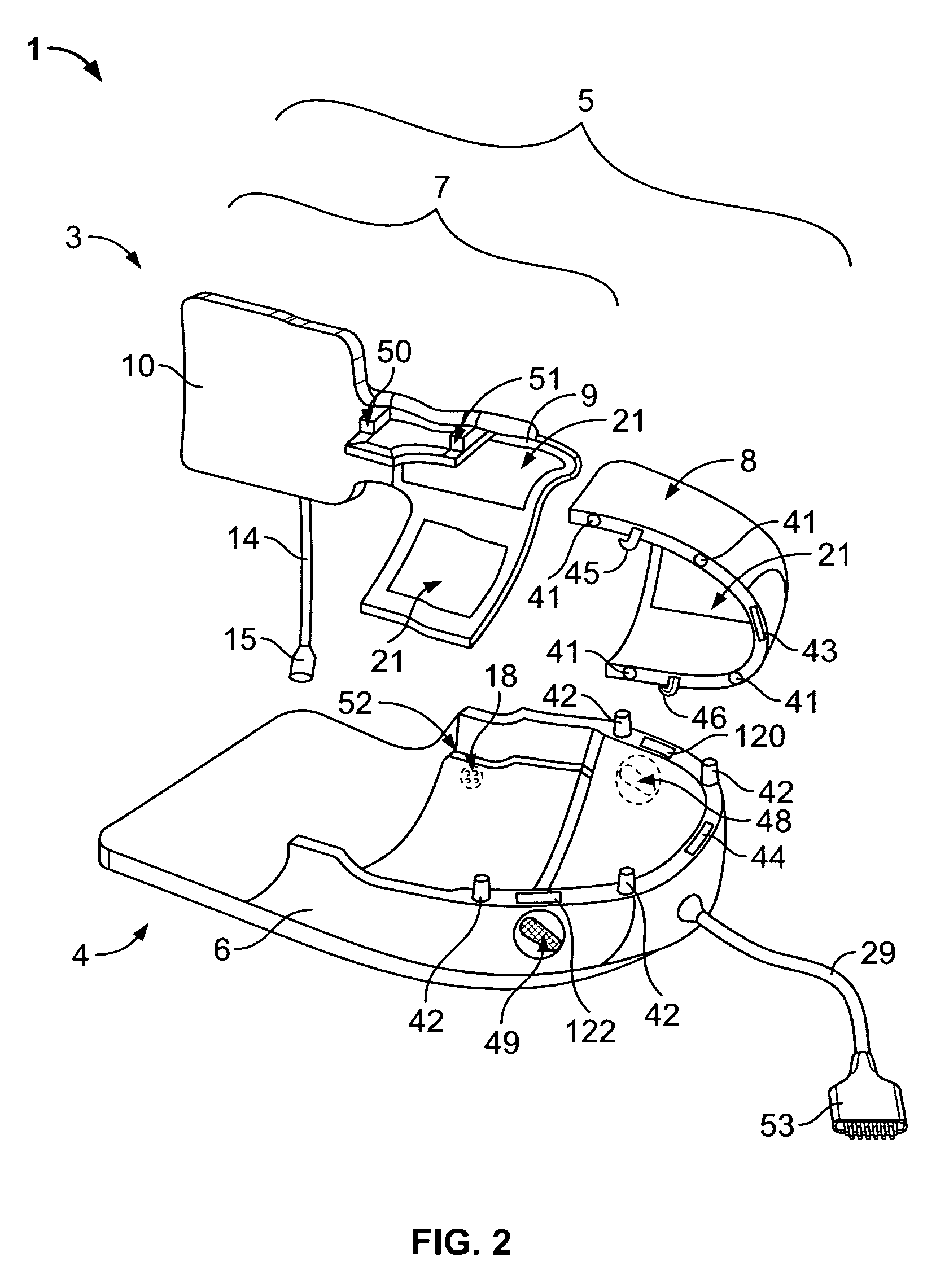
[0048]Various embodiments of the present invention provide a RF array coil system as shown generally in FIGS. 1 and 5. Referring first to FIG. 1, the RF array coil system 1 of present invention includes an anterior coil section 3 and a posterior coil section 4. The anterior coil section 3 includes a main anterior coil section 5 and a secondary anterior coil section 24. The main anterior coil section 5 further includes a generally dome-shaped anterior brain coil section 8 that may be provided, for example, on a rigid former and a separate anterior neck-torso coil section 7 having an anterior neck coil 9 and an anterior torso coil 10, which may, for example, be provided on a flexible / semi-flexible former. The secondary anterior coil section 24 also may be provided, for example, on a flexible / semi-flexible former.

[0049]The posterior coil section 4 includes a main posterior coil section 6 and a secondary posterior coil section 25. The main posterior coil section 6 further includes a dom...


PUM


Abstract

A RF array coil system and method for magnetic resonance imaging are provided. The array coil system includes an anterior coil section having a main anterior coil section and at least one secondary anterior coil section removably attachable to the main anterior coil section. The array coil system further includes a posterior coil section having a main posterior coil section and at least one secondary posterior coil section removably attachable to the main posterior coil section.

Description

CROSS REFERENCE TO RELATED APPLICATIONS[0001]This application claims priority to and the benefit of the filing date of U.S. Provisional Application No. 60 / 523,774 filed on Nov. 19, 2003 and which is hereby incorporated by reference in its entirety.BACKGROUND OF THE INVENTION[0002]This invention relates generally to Magnetic Resonance Imaging (MRI) systems, and more particularly, to a Radio-Frequency (FR) coils in such MRI systems.[0003]Magnetic Resonance Imaging (MRI) utilizes hydrogen nuclear spins of the water molecules in the human body, which are polarized by a strong, uniform, static magnetic field of a magnet. This magnetic field is commonly referred to as B0 or the main magnetic field. The magnetically polarized nuclear spins generate magnetic moments in the human body. The magnetic moments point in the direction of the main magnetic field in a steady state, but produce no useful information if these magnetic moments are not disturbed by any excitation.[0004]The generation of...

Claims


Application Information

Patent Timeline
Patent Type & Authority Patents(United States)
IPC IPC(8): A61B5/05G01R33/3415
CPCG01R33/3415G01R33/34084
Inventor CHAN, PEI H.PETROPOULOS, LABROS
Owner GENERAL ELECTRIC CO
Why Eureka
Try Eureka