
Wheel brake for a vehicle and a vehicle comprising the wheel brake

a technology of a vehicle and a wheel, which is applied in the direction of brake types, mechanical devices, brakes with axial engagement, etc., can solve the problems of increased heat generation, inability to control the diversion of the discs, and higher need for cooling by lubricating oil, so as to reduce material cost and assembly work, and efficient separation of the two adjacent discs

Inactive Publication Date: 2011-11-01
VOLVO CONSTR EQUIP AB
View PDF11 Cites 8 Cited by
  • Summary
  • Abstract
  • Description
  • Claims
  • Application Information

AI Technical Summary

Benefits of technology

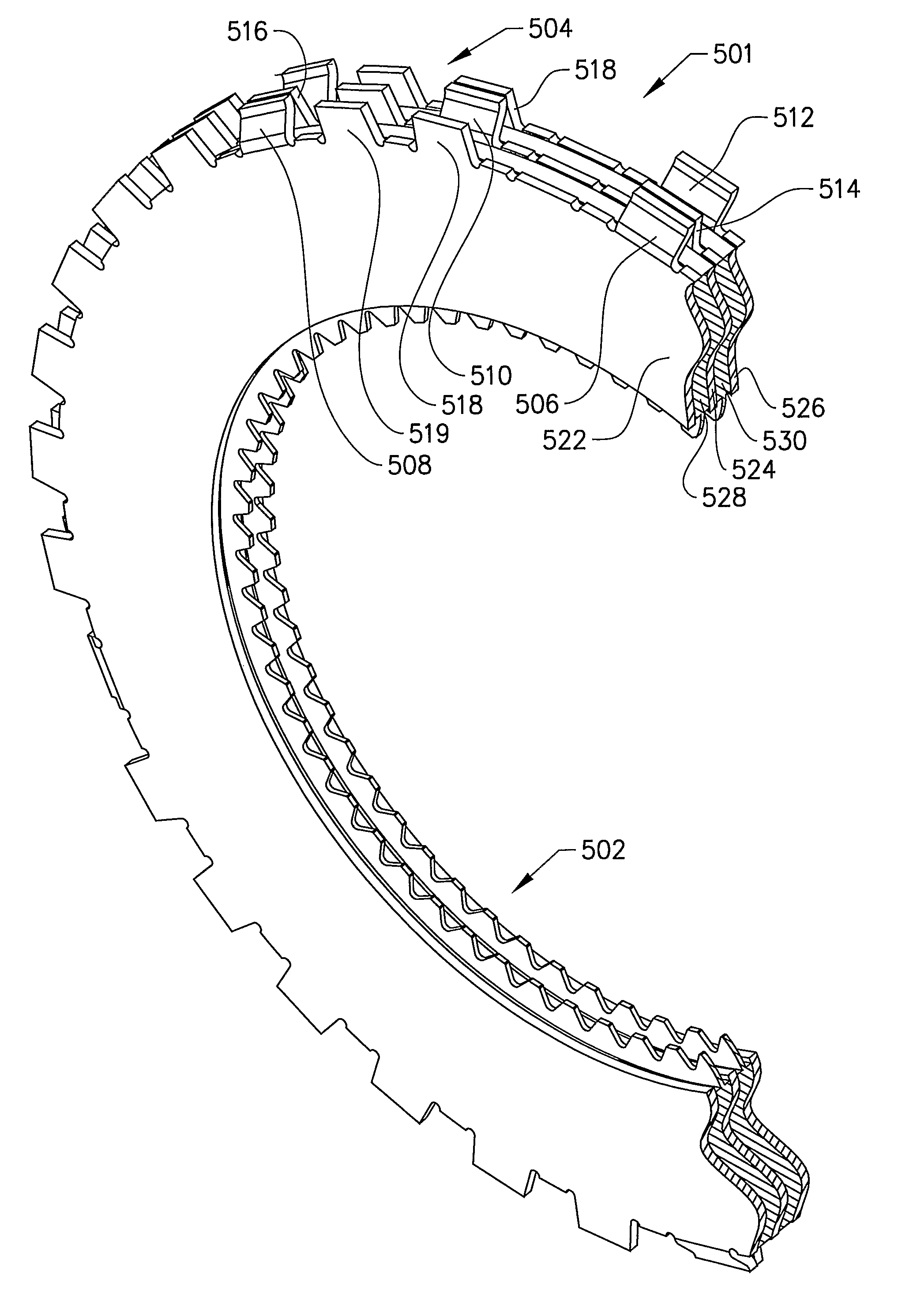
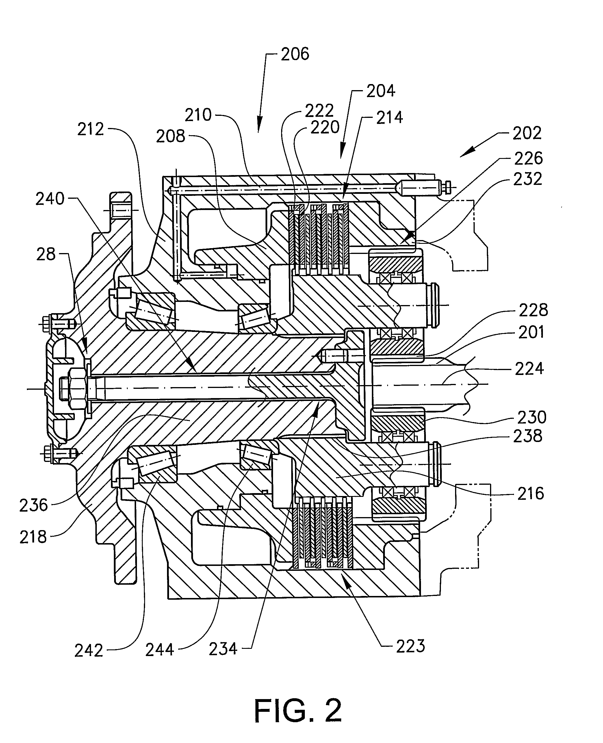
The invention is about a brake for a vehicle's wheel that improves energy efficiency during operation. It includes a brake disc unit with two sets of discs that are arranged in an alternating manner. When the brakes are activated, the discs in the first set are clamped together, while the discs in the second set are prevented from rotation. However, when the brakes are deactivated, the discs in the second set may not be in complete contact with each other, leading to wear and increased fuel consumption. To solve this problem, the brake disc unit includes a separator element that keeps the discs in the second set at least partially separated when the brakes are deactivated. This results in more efficient energy consumption and reduced wear and maintenance.

Problems solved by technology

The discs are solely allowed to diverge upon deactivation by retracting the activation means, but the diversion of the discs is not controlled.
Further, when the vehicle is operated on a sloping ground, the brake disc unit will be tilted and the discs may be displaced towards each other due to gravity and come into contact with each other.
If the discs are in contact during propulsion they are subject to considerable wear, at the same time as the generation of heat is increased.
This leads to a higher need of cooling by lubricating oil, a higher fuel consumption and a more frequent maintenance.

Method used


Image

  • Wheel brake for a vehicle and a vehicle comprising the wheel brake
  • Wheel brake for a vehicle and a vehicle comprising the wheel brake
  • Wheel brake for a vehicle and a vehicle comprising the wheel brake

Examples


Embodiment Construction

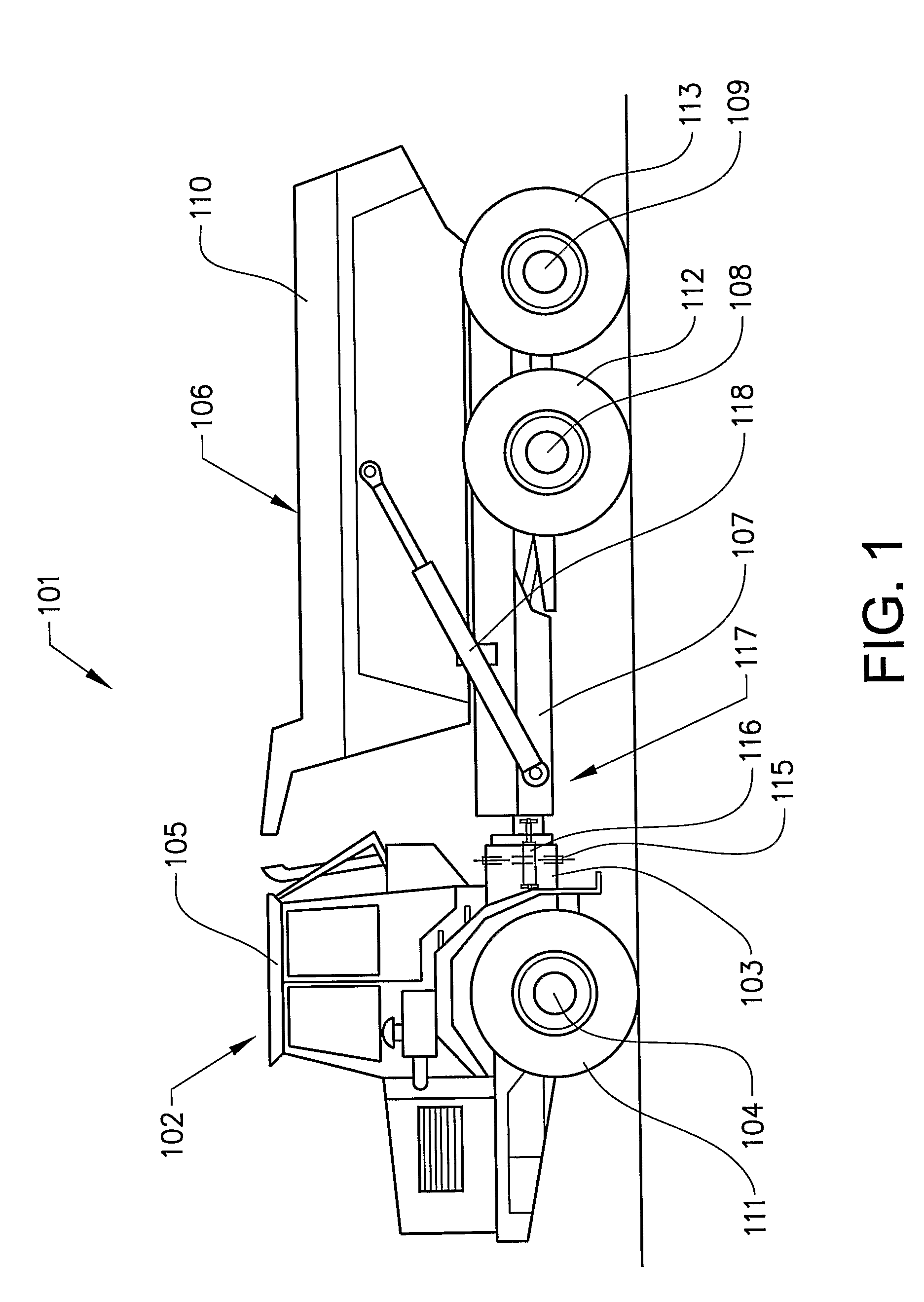
[0019]FIG. 1 illustrates a frame-steered work vehicle in the form of an articulated hauler 101. The articulated hauler 101 comprises a forward vehicle section 102 comprising a forward frame 103, a front wheel axle 104 a power source in the form of an engine (not shown) for propelling the vehicle and a cab 105. The articulated hauler 101 also comprises a rear vehicle section 106 comprising a rear frame 107, a forward bogie axle 108, a rear bogie axle 109 and a tiltable load-carrying platform 110. Each axle comprises a left ground engagement element 111, 112, 113 and a right ground engagement element (not shown) in the form of wheels having rubber tyres.

[0020]The forward frame 103 is connected to the rear frame 107 by means of an articulation joint 115 allowing the forward vehicle section 102 and the rear vehicle section 106 to pivot relative to one another about a vertical axis. A pair of actuators in the form of hydraulic cylinders 116 is arranged one on each side of the articulatio...


PUM


Abstract

A wheel brake for a vehicle including a brake disc unit adapted to brake the rotation of a rotation element, which is adapted to be drivingly connected to the wheel. The brake disc unit includes a first set of discs and a second set of discs arranged in an alternating manner in an axial direction. The discs in the first disc set are adapted to be rotationally rigidly connected to the rotation element. The brake disc unit includes at least one separator element, which is adapted to keep a sufficient distance between two adjacent discs of one of the disc sets for an intermediate disc from the other disc set to rotate at least substantially freely relative to the spaced discs when the brake disc unit is in a deactivated condition.

Description

BACKGROUND AND SUMMARY[0001]The invention is related to a wheel brake for a vehicle comprising a brake disc unit adapted to brake the rotation of a rotation element, which is adapted to be drivingly connected to the wheel, wherein the brake disc unit comprises a first set of discs and a second set of discs arranged in an alternating manner in an axial direction, wherein the discs in said first disc set are adapted to be rotationally rigidly connected to said rotation element. The invention also relates to a vehicle comprising the wheel brake.[0002]This type of disc brake is commonly used at each wheel of a work vehicle. The term “work vehicle” comprises different types of material handling vehicles like construction machines, such as a wheel loader, an articulated hauler, a backhoe loader, a motor grader and an excavator. Further terms frequently used for work vehicles are “earth-moving machinery” and “off-road work machines”. The work vehicles are for example utilized for construct...

Claims


Application Information

Patent Timeline
Patent Type & Authority Patents(United States)
IPC IPC(8): F16D55/36
CPCF16D55/36F16D2065/1396F16D2121/02
Inventor STRANDBERG, JONNYPOPESCU, DAN
Owner VOLVO CONSTR EQUIP AB
Learn More