Fuel cell system and fuel cell starting method

a fuel cell and fuel cell technology, applied in the field of fuel cell systems, can solve the problems of inability to achieve instantaneously switching from a high-concentration aqueous methanol solution to a low-concentration aqueous methanol solution, inability to achieve operation at an optimum concentration, etc., to achieve the effect of shortening the time taken, accelerating heat generation, and raising the temperature of the power generation cell

Inactive Publication Date: 2007-09-13
SONY CORP
View PDF0 Cites 10 Cited by
  • Summary
  • Abstract
  • Description
  • Claims
  • Application Information

AI Technical Summary

Benefits of technology

[0012] According to the method of starting a fuel cell in the present invention, in the fuel cell system the high-concentration fuel is supplied to the negative electrode side, whereby the high-concentration fuel can be brought into reaction with the oxidizer supplied to the positive electrode side, and the temperature of the power generation cell can be thereby raised. In this instance, heat generation can be accelerated by suppressing the quantities of the high-concentration fuel and the oxidizer supplied to the power generation cell to lower levels. This makes it possible to shorten the period of time taken to raise the temperature of the power generation cell in starting the fuel cell system. In addition, since the temperature of the power generation cell can be raised in a short time, the capacity of an auxiliary battery used when the temperature of the power generation cell is low can be reduced, whereby the fuel cell system can be reduced in size.
[0013] In the fuel cell system according to the present invention, the low-concentration fuel for performing mainly a power generation reaction and the high-concentration fuel for performing mainly the power generation reaction and a reaction for raising the temperature of the power generation cell are respectively stored in separate storage vessels, whereby the fuel supplied to the negative electrode can be instantaneously switched according to the temperature of the power generation cell. This makes it possible to perform an operation at a constantly optimum concentration. In addition, by supplying the high-concentration fuel from the negative electrode to the positive electrode through the electrolyte, the high-concentration fuel can be supplied dispersedly, whereby local heat generation can be prevented. Besides, it is possible to prevent the adhesion of water to the positive electrode which might be generated when the fuel is supplied directly to the positive electrode. Further, in the fuel cell system according to the present invention, the low-concentration fuel controlled to such a concentration as to enable an efficient power generation reaction is stored in the first storage vessel, it is possible, by supplying the power generation cell with the fuel only from the first storage vessel in normal operation, to supply the low-concentration fuel having a stable concentration, and thereby to perform stable power generation. In addition, since it is unnecessary to control the fuel concentration in the passage, there is no need for providing a fuel spray nozzle. Furthermore, by arranging the first storage vessel and the second storage vessel separately, the system can be designed according to frequencies of use of both storage vessels, and the fuels can be used without wasting. In addition, the concentrations of the fuels being stored can be regulated according to the environments of use. Besides, the first storage vessel and the second storage vessel are individually detachable, and they can be replaced.
[0014] According to the method of starting a fuel cell in the present invention, in the fuel cell system the high-concentration fuel is supplied to the negative electrode side, whereby the high-concentration fuel can be reacted with the oxidizer supplied to the positive electrode side, so as to raise the temperature of the power generation cell. In this instance, heat generation can be accelerated by suppressing the quantities of the high-concentration fuel and the oxidizer supplied to the power generation cell to low levels. This makes it possible to shorten the period of time taken to raise the temperature of the power generation cell in starting the fuel cell system. In addition, since the temperature of the power generation cell can be raised in a short time, the capacity of an auxiliary battery used when the temperature of the power generation cell is low can be reduced, and the fuel cell system can be reduced in size.

Problems solved by technology

In this system, however, the concentration of the aqueous methanol solution supplied to the anode cannot be lowered unless the methanol in the aqueous methanol solution is consumed in the power generation cell.
Therefore, when the temperature of the power generation cell is raised, the switching from a high-concentration aqueous methanol solution to a low-concentration aqueous methanol solution cannot be instantaneously achieved even if the spraying of methanol from the spray nozzle is stopped.
Furthermore, this system has the problem that an operation at an optimum concentration cannot always be realized.
Therefore, even when the temperature of the power generation cell is raised above a predetermined temperature, an efficient reaction cannot be achieved because the temperature of the power generation cell as a whole is not uniform.
Besides, the method described in Japanese Patent Laid-open No. 2002-075414 has the problem that water in the aqueous methanol solution fed to the cathode would adhere to the cathode.
Since the power generation reaction takes place at the interface between electrode and electrolyte, the adhesion of water to the cathode reduces the amount of oxygen making contact with the cathode, thereby lowering the efficiency of the power generation reaction.

Method used


Image

  • Fuel cell system and fuel cell starting method
  • Fuel cell system and fuel cell starting method
  • Fuel cell system and fuel cell starting method

Examples


Embodiment Construction

[0018] Now, a fuel cell system and a fuel cell starting method in the fuel cell system according to the present invention will be described in detail below, referring to the drawings. Incidentally, the present invention is not limited to or by the following description, and various modifications can be made appropriately within the scope of the gist of the invention.

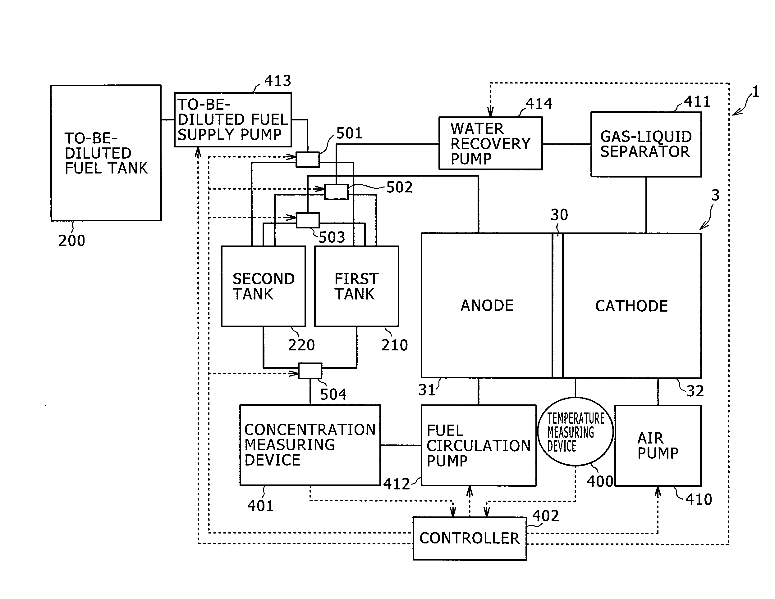
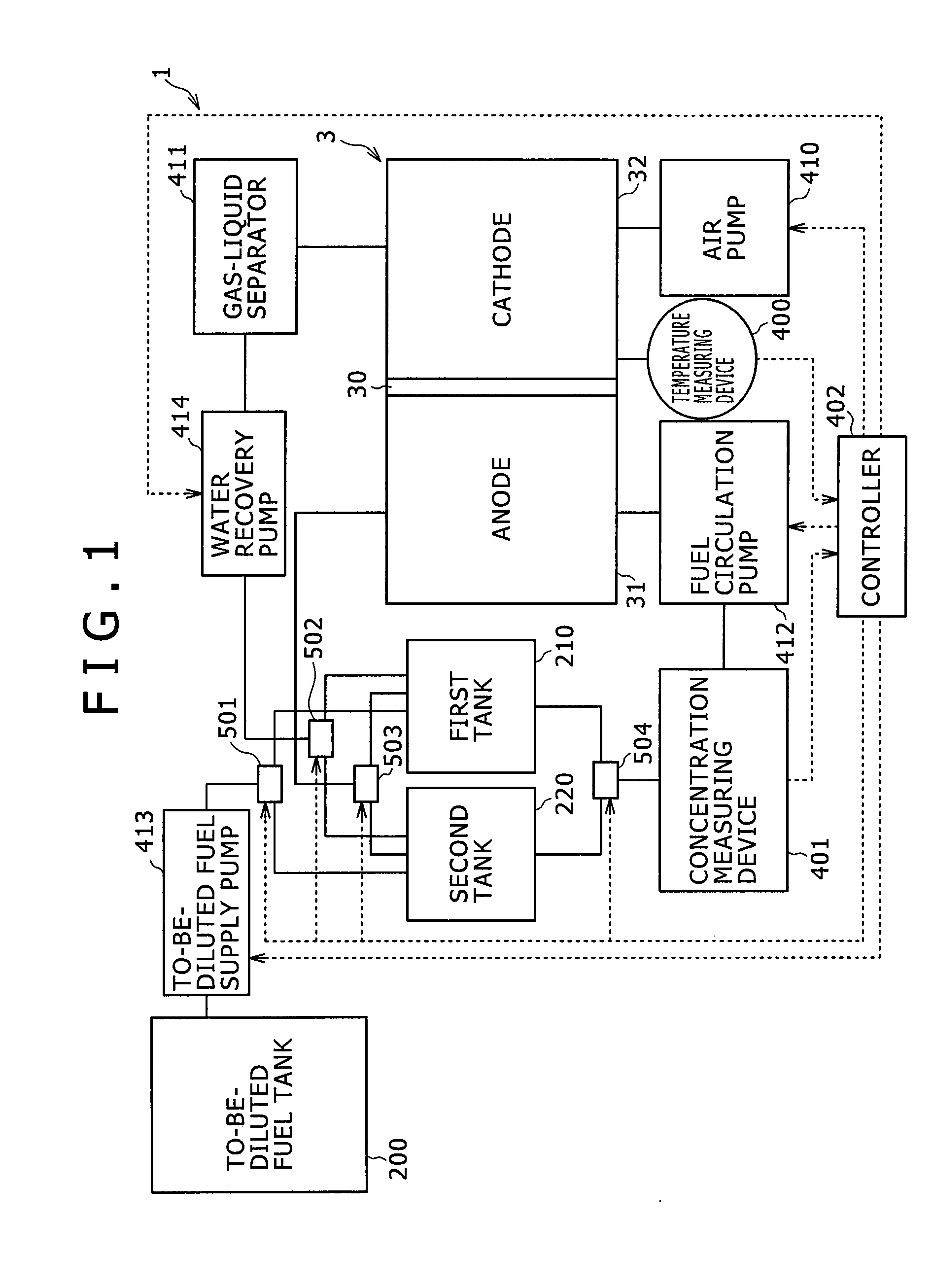
[0019]FIG. 1 is a block diagram showing an example of the configuration of the fuel cell system in the present invention. The fuel cell system 1 in the present invention includes a fuel cell 3 having an electrolyte film 30 sandwiched between a pair of electrodes composed of an anode 31 as a negative electrode and a cathode 32 as a positive electrode, a first tank 210 as a first storage vessel for storing a low-concentration aqueous methanol solution as a low-concentration fuel utilized mainly for a power generation reaction in a power generation cell 3, and a second tank 220 as a second storage vessel for storing a high...


PUM

PropertyMeasurementUnit
operating temperatureaaaaaaaaaa
temperatureaaaaaaaaaa
concentrationaaaaaaaaaa

Abstract

It is an object of the present invention to provide a system in which a fuel cell can be operated by use of a fuel having a constantly optimum concentration. It is another object of the present invention to shorten the time taken in starting a fuel cell. A low-concentration fuel for performing mainly a power generation reaction and a high-concentration fuel for performing mainly the power generation reaction and a reaction for raising the temperature of a power generation cell are stored respectively in separate storage vessels, whereby the fuel supplied to a negative electrode can be instantaneously changed over according to the temperature of the power generation cell. This makes it possible to perform an operation at a constantly optimum fuel concentration. In addition, since it is possible to raise the temperature of the power generation cell in a short time, it is possible to reduce the capacity of an auxiliary battery used when the temperature of the power generation cell is low, and to reduce the fuel cell system in size.

Description

TECHNICAL FIELD [0001] The present invention relates to a fuel cell system, and to a method of starting the fuel cell system. BACKGROUND ART [0002] A fuel cell is a power generation element for generating electric power by an electrochemical reaction between a fuel gas, such as hydrogen or methanol, and an oxidizer gas such as oxygen. The fuel cell, in which the reaction products generated at the time of power generation is water, has been attracting attention as a power generation element not causing environmental pollution, and the use of the fuel cell, for example, as a driving power source for driving an automobile has been tried. [0003] Fuel cells are classified into various types by the kind of electrolyte or the like, and a representative type which has been known is a fuel cell using a solid polymer electrolyte as the electrolyte. The solid polymer electrolyte type fuel cell is promising as a driving power source for electronic apparatuses, since it can be reduced in cost, i...

Claims


Application Information

Patent Timeline
Patent Type & Authority Applications(United States)
IPC IPC(8): H01M8/04H01M8/10
CPCH01M8/04186H01M8/04208Y02E60/523H01M8/04291H01M8/1011H01M8/04268Y02E60/50
Inventor KANAI, TSUYOSHISUDO, GO
Owner SONY CORP
Why Eureka
Try Eureka