Compensation of actinic radiation intensity profiles for three-dimensional modelers

a three-dimensional modeler and intensity profile technology, applied in the field of parts creation using a three-dimensional modeler, can solve the problems of reducing the amount of actinic radiation that is projected by the modeler over time, and modelers having such modelers may produce parts with undesirable parts qualities, so as to reduce the build time of parts

Active Publication Date: 2011-11-01
3D SYST INC
View PDF76 Cites 32 Cited by
  • Summary
  • Abstract
  • Description
  • Claims
  • Application Information

AI Technical Summary

Benefits of technology

[0006]The present invention provides methods and apparatus for three-dimensional modelers to compensate for imager performance. More particularly, the methods and apparatus of the present invention provide for controlled use of imagers that provide varied amounts of actinic radiation over the two-dimensional area of the image plane and / or imagers that provide varied amounts of actinic radiation over a period of time. Certain embodiments of the present invention determine an intensity profile of the actinic radiation projected by the imager to provide a plurality of patterns of actinic radiation to selectively cure the layer of solidifiable liquid material, rather than provide a single pattern of actinic radiation corresponding to the complete cross-section as conventional three-dimensional modelers typically do. In addition, other embodiments of the present invention adjust the position of the part, relative to the image plane, based upon the intensity profile in order to reduce the build time for parts produced by the three-dimensional modeler.
[0008]Another exemplary embodiment of the present invention determines the intensity profile of the actinic radiation projected from the imager and positions a center of the part (or a center of a plurality of parts, if applicable) proximate a portion of the intensity profile defining the highest intensity of the actinic radiation. Positioning the part where the greatest intensity of actinic radiation is projected will generally enable the three-dimensional modeler to produce the part more quickly by requiring less time to selectively cure each layer of the part (regardless of the number of patterns projected for each layer). Conventional three-dimensional modelers typically default the position of the part at the center of the image plane or at a corner or side of the image plane regardless of the intensity of the actinic radiation, so positioning the part where the highest intensity of actinic radiation is projected will enable the part to be produced faster, thus increasing the throughput of the three-dimensional modeler.
[0010]Still further embodiments of the present invention include an intensity profiler within the three-dimensional modeler to allow automatic determination of the intensity profile and / or automatic monitoring of the intensity profile to determine overall changes in the intensity of the imager and / or changes in the intensity profile itself. Such an intensity profiler is generally housed within or on the three-dimensional modeler and is positioned such that it is able to measure the intensity profile but such that it will not adversely affect the selective curing of the solidifiable liquid material of which the parts are produced.

Problems solved by technology

However, certain imagers do not project an equivalent amount of actinic radiation over the two-dimensional area of the image plane and / or the amount of actinic radiation that is projected by the imager diminishes over time.
Therefore, three-dimensional modelers having such imagers may produce parts that possess undesirable part qualities (aesthetic and / or structural) resulting from over-curing and / or under-curing of the material selectively cured to form the part.

Method used


Image

  • Compensation of actinic radiation intensity profiles for three-dimensional modelers
  • Compensation of actinic radiation intensity profiles for three-dimensional modelers
  • Compensation of actinic radiation intensity profiles for three-dimensional modelers

Examples


Embodiment Construction

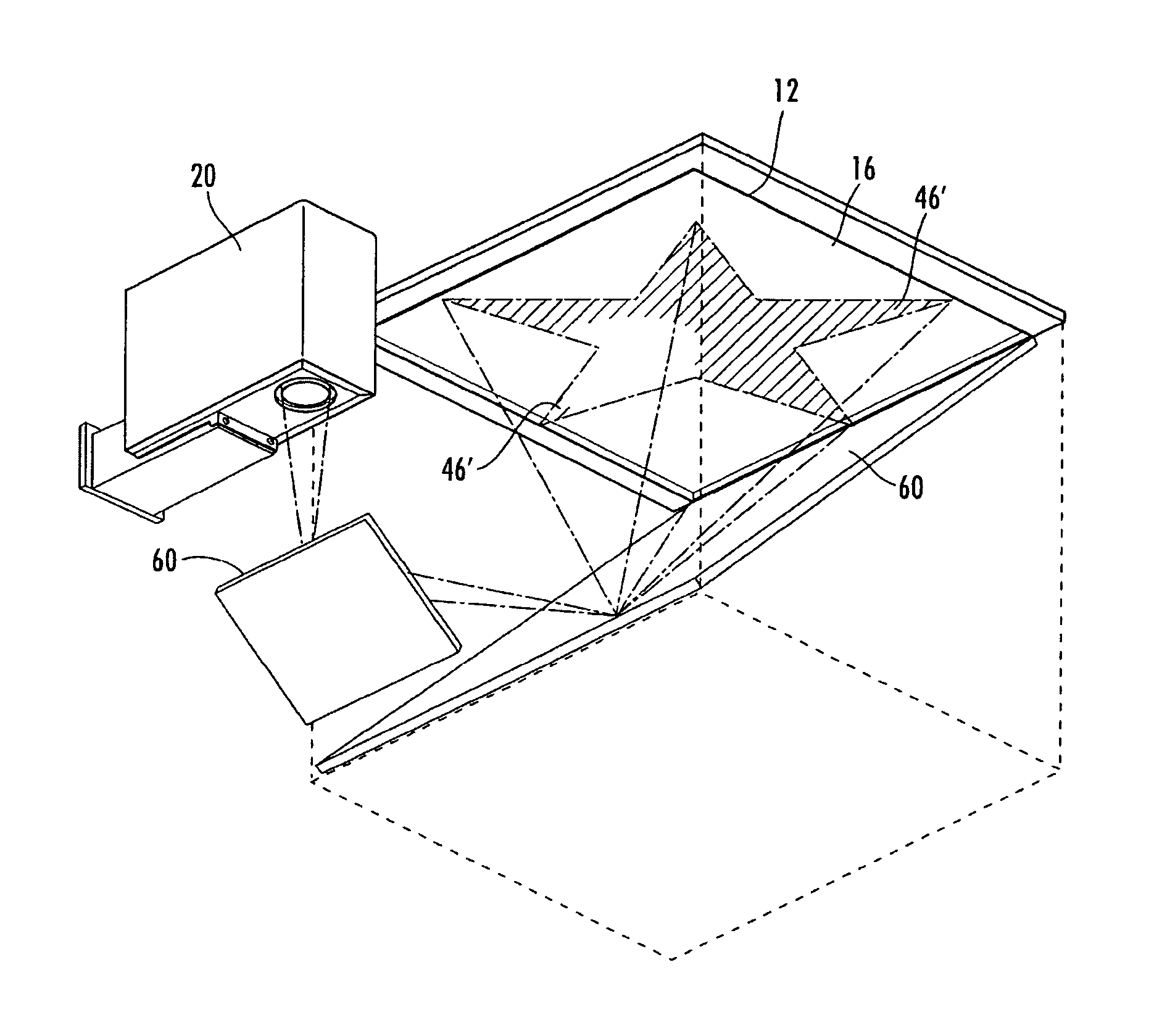
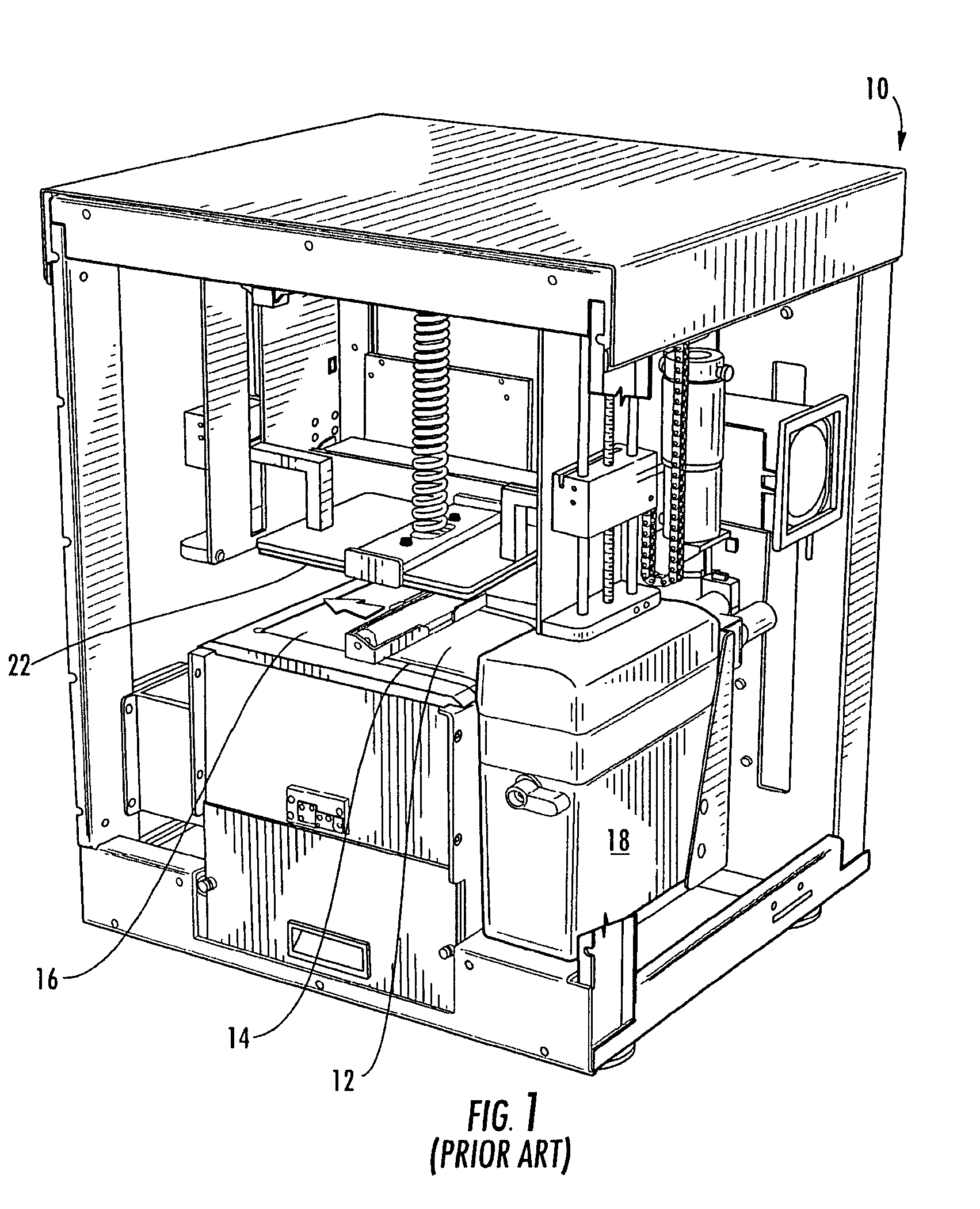
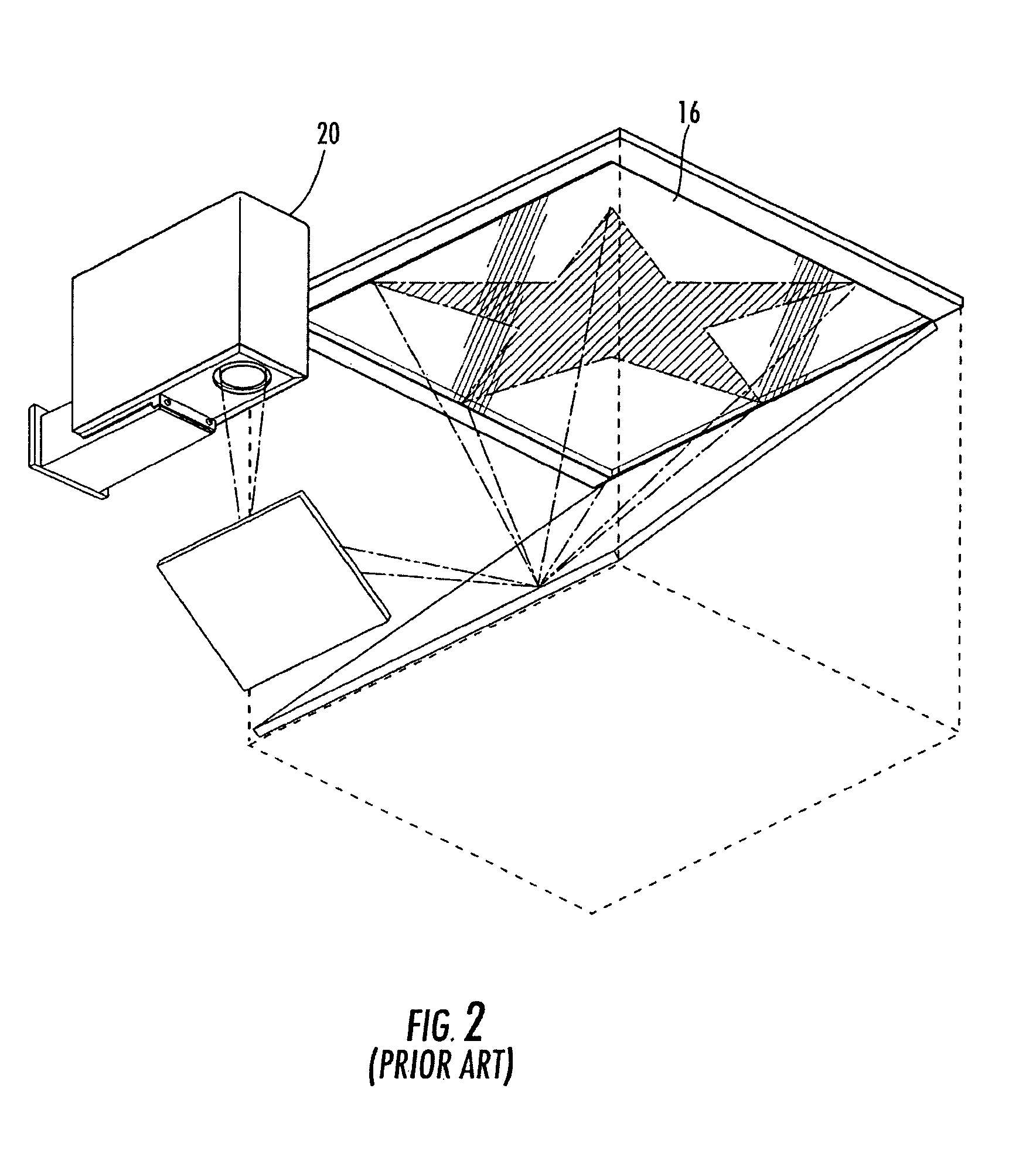
[0023]The present invention now will be described more fully hereinafter with reference to the accompanying drawings, in which some, but not all embodiments of the invention are shown. Indeed, the invention may be embodied in many different forms and should not be construed as limited to the embodiments set forth herein; rather, these embodiments are provided so that this disclosure will satisfy applicable legal requirements. Although the methods and apparatus are described and shown in the accompanying drawings with regard to a three-dimensional modeler utilizing the film transfer imaging technique, it is envisioned that the methods and apparatus of the present invention may be applied to any now known or hereafter devised three-dimensional modeler in which it is desired to cure material with a substantially equivalent (or otherwise controlled) amount of actinic radiation per surface area in order to produce three-dimensional parts. Like numbers refer to like elements throughout.

[0...


PUM

PropertyMeasurementUnit
timeaaaaaaaaaa
surface areaaaaaaaaaaa
imagingaaaaaaaaaa

Abstract

There is provided methods and apparatus for compensation of intensity profiles of imagers used in three-dimensional modelers. The intensity profile of the actinic radiation projected from the imager is determined by a variety of techniques, including but not limited to manually operated sensors, exposed and scanned actinic radiation-sensitive paper, and intensity profilers. Once the intensity profile of the imager is determined, each layer of the solidifiable liquid material is cured by projecting a plurality of patterns (as opposed to a single pattern) defining the two-dimensional cross-section of the part being cured. The patterns vary in duration, number, and / or shape to correlate to the intensity profile so that a single layer of selectively cured solidifiable liquid material is cured with a substantially equivalent (or otherwise controlled) amount of actinic radiation per unit of surface area to provide generally controlled and consistent part quality.

Description

FIELD OF THE INVENTION[0001]The present invention is related to the creation of parts using a three-dimensional modeler, and more particularly, to methods and apparatus for providing substantially consistent and / or controlled curing of the solidifiable liquid material.BACKGROUND OF THE INVENTION[0002]A number of additive manufacturing technologies presently exist for the rapid creation of models, prototypes, and parts for limited run manufacturing or other applications. Such parts can be made using solid freeform fabrication techniques, which include but are not limited to stereolithography, selective deposition modeling, laminated object manufacturing, selective phase area deposition, multi-phase jet solidification, ballistic particle manufacturing, fused deposition modeling, particle deposition, laser sintering, film transfer imaging, and the like. Some, but not all, of these techniques are performed by three-dimensional modelers that provide a layer of solidifiable liquid materia...

Claims


Application Information

Patent Timeline
Patent Type & Authority Patents(United States)
IPC IPC(8): B29C35/04
CPCB29C67/007B05C9/12B29C64/129B33Y30/00B33Y50/02B29C64/393B33Y10/00B33Y50/00
Inventor WANG, HONGQING V.KUEK, SOON-CHUNHULL, CHARLES W.GREGORY, II, RICHARD ORAKEREKES, THOMAS ALAN
Owner 3D SYST INC
Why Eureka
Try Eureka