Oven-controlled crystal oscillator

a technology of crystal oscillator and oven, which is applied in the field of oven-controlled crystal oscillator, can solve the problems of preventing the temperature control of the crystal unit from properly following, difficulty in reducing so as to improve the efficiency of heat conduction from the heating film resistor to the crystal unit and reduce the height dimension of the crystal oscillator

Inactive Publication Date: 2011-11-01
NIHON DEMPA KOGYO CO LTD
View PDF8 Cites 14 Cited by
  • Summary
  • Abstract
  • Description
  • Claims
  • Application Information

AI Technical Summary

Benefits of technology

[0020]An object of the present invention is to provide an oven-controlled crystal oscillator which allows operating temperature control of a crystal unit to properly follow a change in temperature and which can be manufactured so as to have a small size.
[0022]In this configuration, the heating film resistor is provided on the circuit board in an area which lies opposite a bottom surface of the crystal unit which is surface-mounted on the circuit board. Heat generated by the heating film resistor travels uniformly and directly to the bottom surface of the crystal unit. This makes the distribution of temperatures all over the bottom surface of the crystal unit even. Consequently, the efficiency of heat conduction from the heating film resistor to the crystal unit is improved. Thus, the temperature control of the crystal unit can more properly follow a change in temperature.
[0023]Furthermore, in this configuration, since the film resistor, for example, a thick-film resistance element, is used and provided on the surface of the circuit board, the height dimension of the crystal oscillator can be reduced.

Problems solved by technology

This prevents the temperature control of the crystal unit from properly following a change in temperature.
Disadvantageously, the temperature control is still prevented from properly following a change in ambient temperature.
Thus, reducing the height dimension of the crystal oscillator is difficult.

Method used


Image

  • Oven-controlled crystal oscillator
  • Oven-controlled crystal oscillator
  • Oven-controlled crystal oscillator

Examples


first embodiment

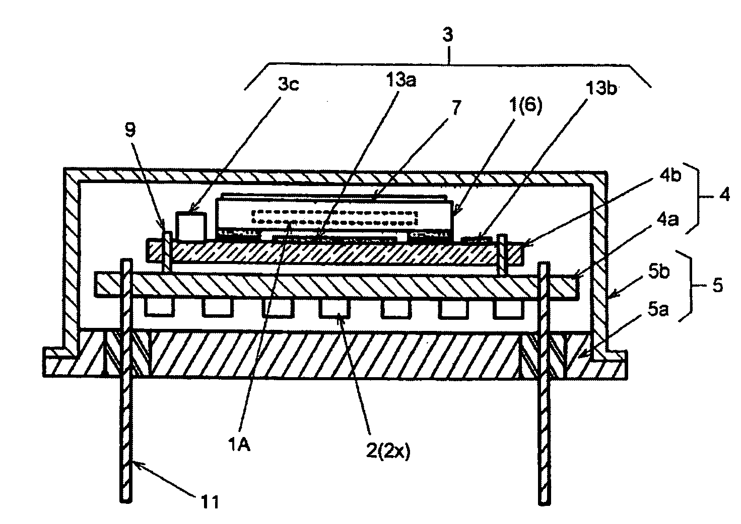
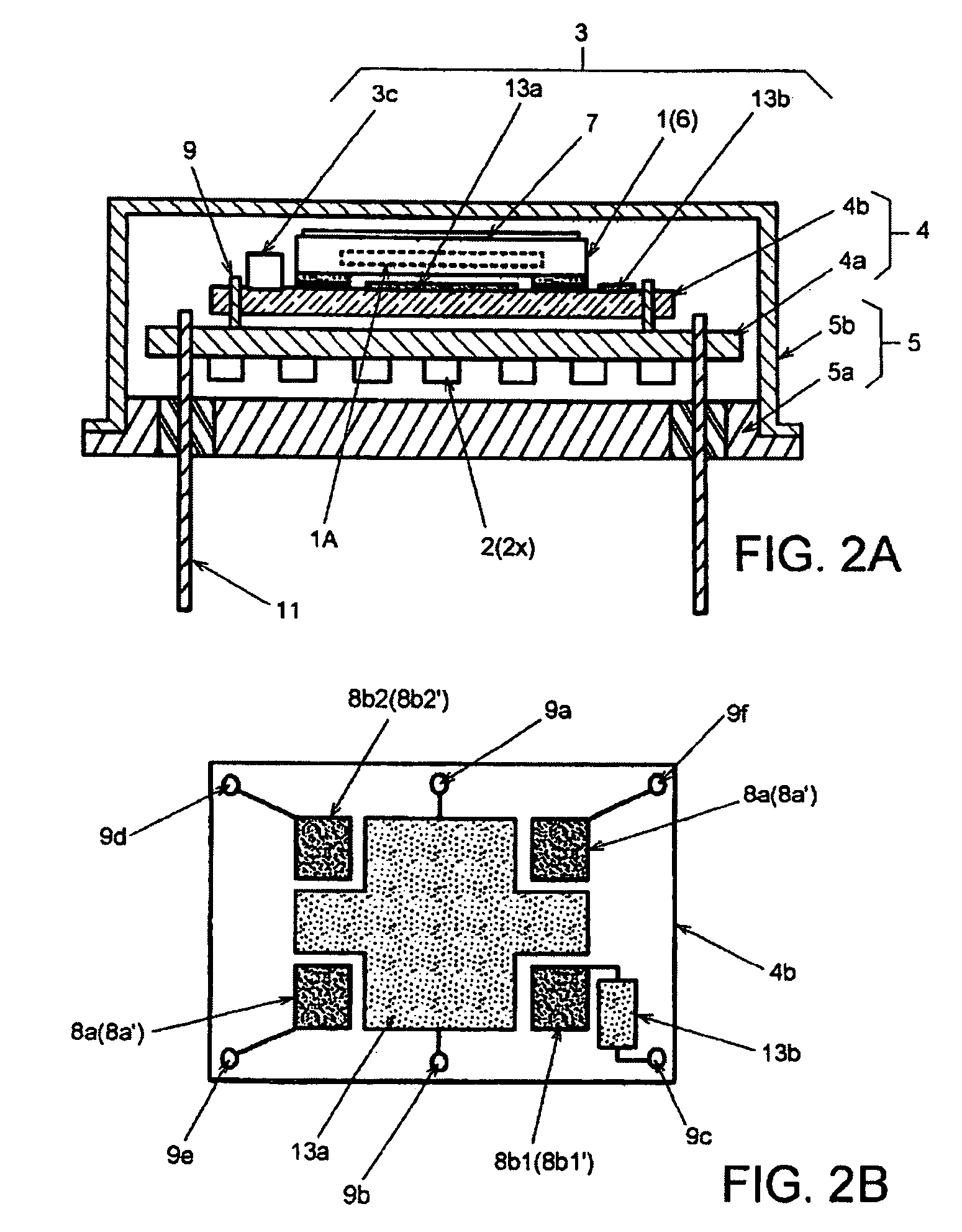
[0037]In FIGS. 2A and 2B showing an oven-controlled crystal oscillator according to the present invention, the same components as those in FIGS. 1A and 1B are denoted by the same reference numerals. Duplicate descriptions will not be repeated below.

[0038]Like the above-described oven-controlled crystal oscillator, an oven-controlled crystal oscillator according to a first embodiment includes, as circuit board 4, first board 4a made up of a glass-epoxy wiring board and second board 4b made up of a ceramic wiring board; first board 4a and second board 4b are arranged in two stages and accommodated in metal container 5. Metal container 5 is made up of metal base 5a and metal cover 5b joined to metal base 5a. A plurality of air-tight terminals 11 are provided so as to penetrate metal base 5a. First board 4a is held by air-tight terminals 11. Second board 4b is held above first board 4a by metal pins 9 which connect second board 4b to first board 4a. Each of first board 4a and second boa...

second embodiment

[0052]In the crystal oscillator second board 4b is stacked on first board 4a made up of a glass-epoxy board without using metal pins. Second board 4b includes heating film resistor 13a and temperature sensitive film resistor 13b on ah upper surface thereof and is made up of ceramics. Circuit elements 2 are provided on the lower surface of first board 4a. Wiring paths (not shown) forming an oscillation circuit and a temperature control circuit are formed on the upper surface of first board 4a and the lower surface of second board 4b via through-holes and board end surfaces. The wiring path on the upper surface of first board 4a is joined to the wiring path on the lower surface of second board 4b by soldering.

[0053]In this configuration, second board 4b is placed directly on first board 4a without using any metal pin. Thus, compared to the configuration of the first embodiment, the configuration of the second embodiment enables a further reduction in the height dimension of the oven-...

fourth embodiment

[0062]This configuration exerts effects similar to those of the The configuration also prevents crystal unit 1 from interfering with circuit elements 2 on insulating base 14 to enable a further reduction in the height of the crystal oscillator.

[0063]An oven-controlled crystal oscillator according to a sixth embodiment of the present invention will be next described. FIG. 7C shows the crystal oscillator according to the sixth embodiment.

[0064]The crystal oscillator according to the sixth embodiment is similar to that according to the fifth embodiment except that no metal pin 9 is used. Specifically, an outer peripheral portion of the top surface of insulating base 14 is thickened so as to form a recess in a central area of the top surface of insulating base 14. Crystal unit 1 and the circuit elements are housed in the recess. To thicken the outer peripheral portion of insulating base 14, the number of glass-epoxy plies laminated together may be increased accordingly.


PUM


Abstract

An oven-controlled crystal oscillator includes a circuit board, a crystal unit surface-mounted on the circuit board, and a temperature control circuit that maintains operating temperature of the crystal unit constant. The temperature control circuit includes a heating resistor, a power transistor that supplies power to a heating resistor, and a temperature sensitive resistor that detects temperature of the crystal unit. The heating resistor is formed, as a film resistor, on a surface of the circuit board in an area thereof in which the crystal unit is located. The temperature sensitive resistor is provided on the circuit board as a film resistor.

Description

BACKGROUND OF THE INVENTION[0001]1. Field of the Invention[0002]The present invention relates to an oven-controlled crystal oscillator that uses a surface-mount type quartz crystal unit, and in particular, to an oven-controlled crystal oscillator that is excellent in responsiveness to a change in temperature.[0003]2. Description of the Related Art[0004]A crystal oscillator includes a crystal unit composed of a quartz crystal blank hermetically encapsulated in a container and an oscillation circuit that uses the crystal unit; the crystal unit and the oscillation circuit are integrated together. The crystal oscillator is used in various electronic apparatuses as a reference source for frequency and time. One of such crystal oscillators is an oven-controlled crystal oscillator that maintains operating temperature of the crystal unit constant. Since the operating temperature of the crystal unit is maintained constant regardless of ambient temperature, the oven-controlled crystal oscilla...

Claims


Application Information

Patent Timeline
Patent Type & Authority Patents(United States)
IPC IPC(8): H03B5/36H03L1/02
CPCH03B5/04H03L1/04H05K1/0212H05K1/167H05K2201/10075H05K2201/10151H05K2201/10166
Inventor ARAI, JUNICHIKASAHARA, KENJI
Owner NIHON DEMPA KOGYO CO LTD
Why Eureka
Try Eureka