Color rotating element displays

a technology of rotating elements and display screens, applied in the field of visual displays, can solve the problems of low reflectance, lack of image quality comparable to that of images printed on paper, and lack of color rotation elements, etc., and achieve the effects of high brightness, contrast and saturation, cost-effective manufacturing, and simplified manufacturing

Active Publication Date: 2011-11-01
COSPHERIC
View PDF70 Cites 13 Cited by
  • Summary
  • Abstract
  • Description
  • Claims
  • Application Information

AI Technical Summary

Benefits of technology

[0008]The present invention provides several new types of color REDs which in many embodiments possess high brightness, contrast, and saturation, can be cost-effectively manufactured and can operate at acceptable voltage. Both multi-color REDs and two-color REDs are provided. Displays having more than two colors but less than full color spectrum can also be manufactured using methods provided herein.
[0009]The present invention discloses four new types of multi-color rotating element displays. In some embodiments the displays are based on combining distinct sets of two-color microspheres, also known as bichromal microspheres, where each microsphere is composed of two hemispheres that are electrically and optically anisotropic. These distinct sets of microspheres vary not only in optical properties but also in how they respond to electromagnetic field, allowing manufacturing of a device with unique functionality of multi-color effects without the use of complex electronics. In some embodiments, the sets of bichromal microspheres of different particle size are combined. The present invention uses bichromal microspheres in new ways in conjunction with new techniques to provide lower-cost reflective displays with multi-color effects capability.
[0010]Provided displays make use of a container matrix that comprises a plurality of cells configured for housing rotating elements (e.g., one element per cell), such that an ordered array of rotating elements in a tightly packed monolayer arrangement is created. The container matrix can be manufactured by known techniques, e.g., by hot embossing, and can then be populated by rotating elements, sealed, and filled with dielectric fluid, to provide a front plane of an RED structure. Arranging rotating elements in a tightly packed monolayer, as opposed to elastomer substrate, significantly simplifies manufacturing, improves brightness and lowers operating voltage of the device.
[0014]In some embodiments the rotatable elements are hemispherically coated spheres, wherein the rotatable elements of different types comprise cores made of glass, polymer or ceramic. In some embodiments, the coatings used for the hemispherically coated elements impart optical and electrical anisotropy to the rotatable elements. In some embodiments, each type of the rotatable elements comprises a hemisphere having a white color. Preferably, the viewable portions of the matrix containing the rotatable elements are white, which can significantly improve the brightness of the display.
[0020]Advantageously, because of facile size-matching between the rotating elements and the cells of the matrix, the described display can be easily manufactured using pre-formed optically anisotropic elements of different sizes and a pre-formed matrix having regions of different-size cells configured to host the optically anisotropic elements of matching sizes.

Problems solved by technology

Rotating element technology, however, failed to produce image quality comparable to that of images printed on paper.
In particular, such displays did not possess the high reflectance of white paper, therefore providing low-contrast images.
Rotating element displays based on elastomer substrate also had limited environmental stability, because plasticized polymer was not capable of withstanding high-temperature or high-humidity conditions.
Further, only few dielectric fluids were suitable for use in gyricon displays, since dielectric fluid in gyricon was serving both as a polymer plasticizer and as a rotation media and therefore had to possess properties suitable for both of these applications.
Rotating element displays are generally limited to black-and-white devices.
While use of color filters in combination with gyricons was described, e.g., in U.S. Pat. No. 7,071,895 issued to Wampler, and in U.S. Pat. No. 5,815,306 issued to Sheridon et al., commercial use of such displays was limited due to manufacturing difficulties and due to low brightness and contrast of the resulting devices.
Since black and white electrophoretic displays in general and gyricon displays in particular have limited brightness in the white state, adding a color filter on top of the display reduces the brightness of the display even further, creating a display with washed out colors and poor readability.
The displays described in these references similarly suffered from manufacturing difficulties and were not successfully commercialized.
Rotating element devices disclosed in these patents involve particles disposed in an elastomer substrate swelled by a plasticizer fluid, where the particles are disposed in random configuration resulting in poor packing density, lower brightness, contrast and saturation of colors in a device.
In addition, the devices described in these patents require complex manufacturing of small multi-segment rotating elements, combining transparent and colored regions.
The major limitation of previously described multi-layer devices based on rotating elements is that the operating voltage required to drive these devices is too high for producing a cost-effective and commercially-viable device.
Multi-layer approach results in rotating element display that is too thick and in operating voltage that is too high for successful commercialization.

Method used


Image

  • Color rotating element displays
  • Color rotating element displays
  • Color rotating element displays

Examples


Embodiment Construction

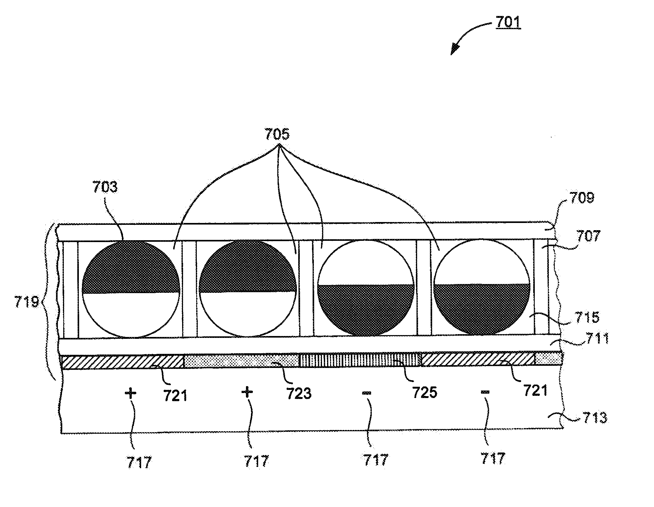
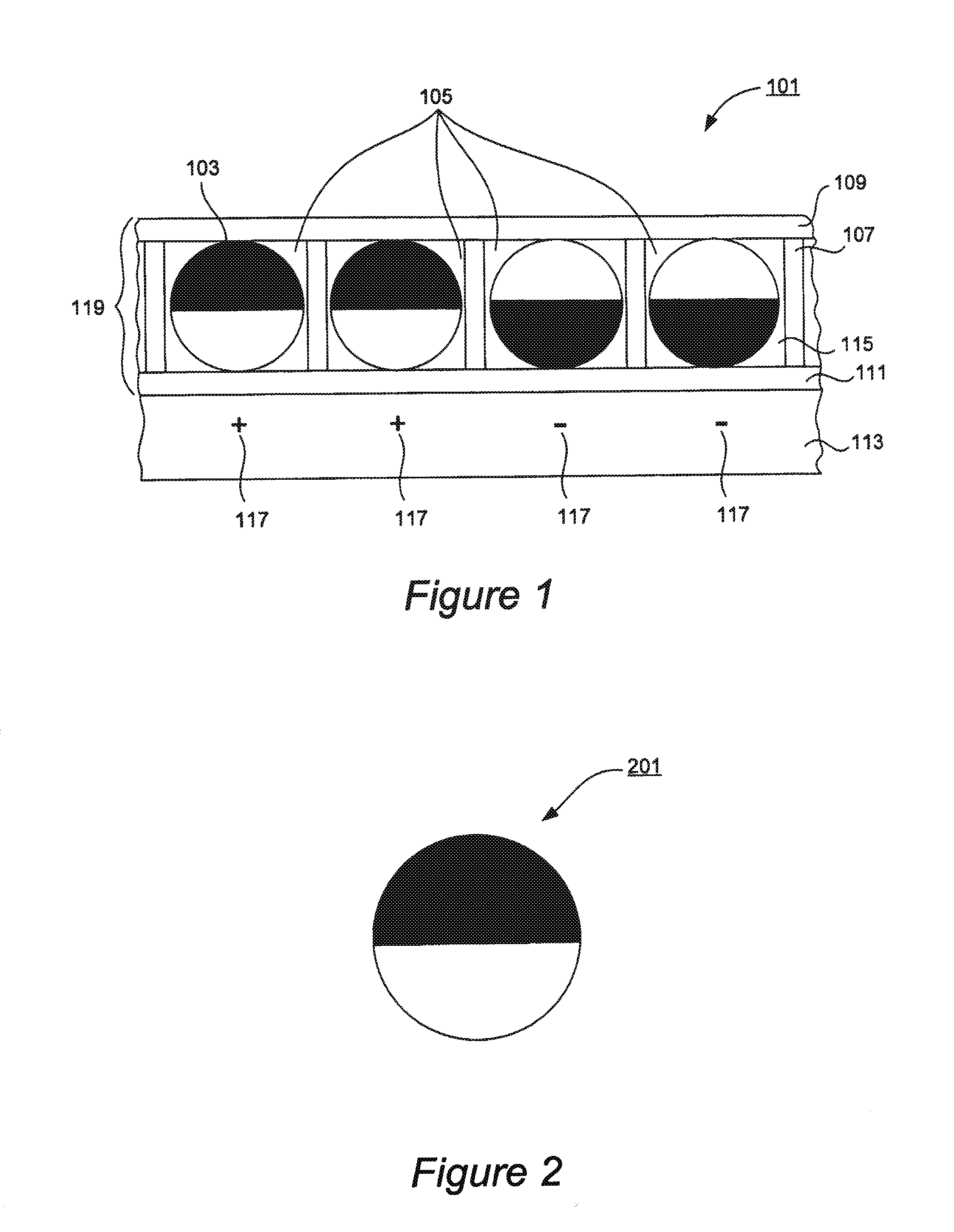
[0052]Color rotating element displays provided herein can be used for a wide variety of applications, including e-books, cell phones and other portable electronics, signage, rigid flat-panel display screens, billboards, color-changing fabrics, specialty films and other applications. In some embodiments, color rotating element displays can be written on and erased, as well as can retain information for a long period of time in the absence of an electric field or other external retaining force. In some embodiments, provided electronic paper displays are preferably thin, lightweight, and durable which allows them to be rolled or folded without the loss of information.

[0053]In some embodiments, provided displays of all four types make use of distinct sets of rotatable elements that respond differently to electromagnetic stimulus. For example, in some embodiments, elements with distinct optical properties will have matched and distinct responses to an electromagnetic stimulus. In one exa...


PUM

PropertyMeasurementUnit
areaaaaaaaaaaa
diameteraaaaaaaaaa
diameteraaaaaaaaaa

Abstract

A rotating element display includes a matrix having discrete regions of cells of different sizes occupied by rotatably disposed optically and electrically anisotropic elements (e.g., electrically anisotropic bichromal spheres). The regions of larger cells are occupied by larger rotating elements having a first combination of optical properties while the regions of smaller cells are occupied by smaller elements having a second combination of optical properties. The rotating elements having different combinations of optical properties are separately addressable by electromagnetic signals that cause rotation of selected optically dissimilar elements and create a desired color image. In a different aspect, a rotating element display includes a plurality of optically anisotropic rotatable elements occupying cells of a transparent matrix, in a configuration where a background color is viewable through the matrix. A color image is created using a combination of background color with optical properties of the rotating elements.

Description

CROSS-REFERENCE TO RELATED APPLICATIONS[0001]This application claims benefit of prior U.S. Provisional Application No. 61 / 184,600 filed Jun. 5, 2009, titled “Color Rotating Element Displays” naming Lipovetskaya et al. as inventors, which is herein incorporated by reference in its entirety and for all purposes.FIELD OF THE INVENTION[0002]The present invention relates to visual displays. Specifically, it relates to electro-optic displays that employ optically and electrically anisotropic rotating elements for generation of images. More specifically, it relates to color rotating element displays.BACKGROUND OF THE INVENTION[0003]Rotating element displays (REDs) are electro-optic displays that employ rotation of optically and electrically anisotropic elements to generate images. The first REDs were developed in the 1970s at Xerox's Palo Alto Research Center. These displays, often referred to as “gyricon” displays, rotating element displays, or twisting ball displays, are typically based ...

Claims


Application Information

Patent Timeline
Patent Type & Authority Patents(United States)
IPC IPC(8): G02B26/00G02F1/03G03G13/00G09G3/34
CPCG02B26/026
Inventor LIPOVETSKAYA, YELENAGOBROGGE, BRIAN
Owner COSPHERIC
Why Eureka
Try Eureka