Multi-band portable SATCOM antenna with integral diplexer

a portable, antenna technology, applied in the direction of polarised antenna unit combinations, substation equipment, transmission, etc., can solve the problem of placing an additional burden on a soldier or other field operator, and achieve the effect of facilitating simultaneous operation of the antenna

Inactive Publication Date: 2011-11-08
KAMIS ISA PRESIDENT
View PDF9 Cites 9 Cited by
  • Summary
  • Abstract
  • Description
  • Claims
  • Application Information

AI Technical Summary

Benefits of technology

[0011]An object of the present invention is to provide a multi-band manpack-portable ultra-high frequency SATCOM radio antenna which includes an integral diplexer that facilitates operation of the antenna in different frequency bands.
[0012]Another object of the invention is to provide a foldable, manpack-portable multi-band UHF antenna which includes an integral diplexer unit contained within a housing extending conformally from the base of the antenna to thus substantially maintain the size, weight, and form factor of antennas for similar applications that require an external diplexer box.
[0013]Another object of the invention is to provide an improvement in manpack portable UHF antennas in which a housing containing an integral diplexer and conformally attachable to the base of the antenna enables multi-band operation off the antenna without the requirement for an external diplexer box.
[0016]Briefly stated, the present invention comprehends an improved man-pack portable ultra-high frequency (UHF) radio antenna for use in transmitting and receiving radio signals between terrestrial locations, and for satellite communications (SATCOM) between terrestrial locations and an earth-orbiting satellite. According to the invention, a foldable, manpack-portable multi-band SATCOM antenna has an integral diplexer which facilitates simultaneous operation of the antenna in different frequency bands. Thus, the antenna according to the present invention enables radio transceivers to be connected directly to the antenna and simultaneously transmit signals at high power levels in two different frequency bands, or transmit high-power signals in a first, up-link frequency band while simultaneously receiving low-power signals in a second, down-link frequency band
[0017]According to the invention, the integral diplexer is contained in a cylindrically shaped housing which mounts conformally to the cylindrically shaped base of a foldable, man-pack portable turnstile type SATCOM antenna. Thus the antenna according to the present invention eliminates the requirements for an external diplexer and interconnecting cables typically required for full-duplex operation of portable radio transceivers in different frequency bands, while retaining a similar form factor and a size only slightly larger than that of prior portable SATCOM antennas.

Problems solved by technology

Thus portable military where line-of-sight communications are not feasible often utilize transmissions between an orbiting earth satellite to provide the needed range and terrain obstruction avoidance.
The requirement for separate external diplexers imposed by prior-art portable SATCOM antennas operated in a full duplex mode places an additional burden on a soldier or other field operator, because of the additional bulk and weight of the external diplexer and cables required to interface the diplexer between a transceiver and a SATCOM antenna.

Method used


Image

  • Multi-band portable SATCOM antenna with integral diplexer
  • Multi-band portable SATCOM antenna with integral diplexer
  • Multi-band portable SATCOM antenna with integral diplexer

Examples


Embodiment Construction

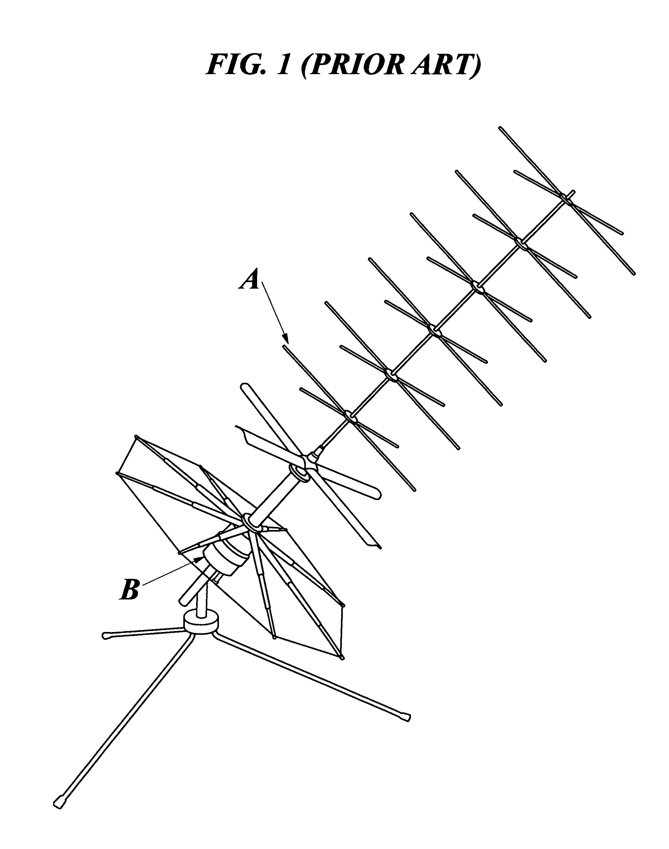
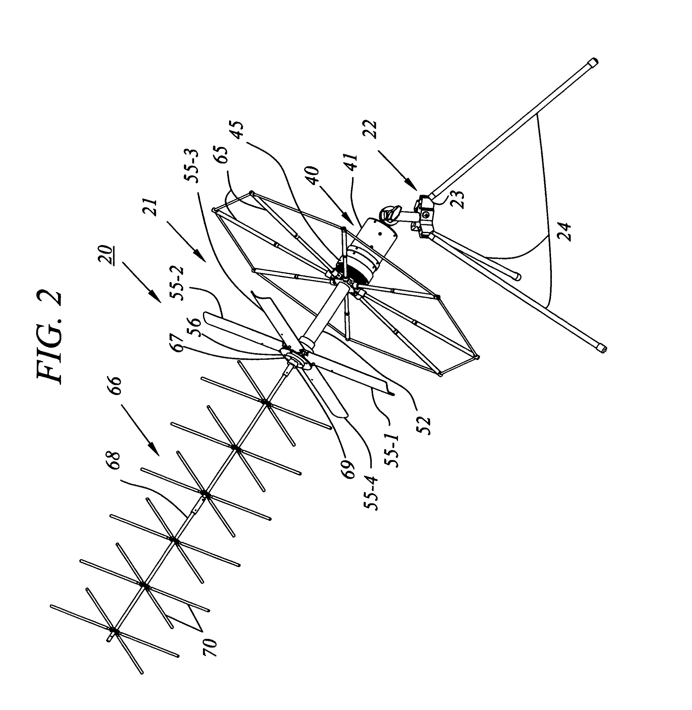
[0038]FIG. 1 illustrates a prior art manpack-portable UHF SATCOM antenna A. FIGS. 2-16 illustrate a multi-band portable SATCOM antenna with integral diplexer according to the present invention.

[0039]Referring first to FIG. 2, it may be seen that a multi-band portable antenna 20 according to the present invention includes an antenna superstructure 21 which is supported at adjustable elevation angles by a tripod 22. Tripod 22 includes a table 23 supported by three tripod legs 24. As shown in FIGS. 2A-2C, the table 23 has generally a polygonal outline with flat and parallel upper and lower surfaces 25, 26. Table 23 has formed in the vertical peripheral wall surface 27 thereof three radially inwardly extending grooves 28 which penetrate lower surface 26 of the table. The three grooves 28 are spaced circumferentially apart at 120-degree intervals. Each groove 28 pivotably retains therein a separate tripod leg, and has therein a detent mechanism which enables the legs to be fixed in a dow...


PUM


Abstract

A man-pack portable, multi-band ultra-high frequency turnstile-type SATCOM radio antenna for transmitting and receiving radio signals between terrestrial locations and an orbiting earth satellite includes a cylindrically shaped antenna superstructure base which has an elongated mast extending forward from a front transverse end wall of the base, and circumferentially spaced apart pairs of radiating elements which extend radially outwards from the mast, each opposed pair comprising in combination an electric dipole antenna which is electrically connected via coaxial cables disposed longitudinally through the mast to zero and ninety degree ports of a hybrid antenna matching network located in the base and having an input port electrically connected to a coaxial antenna base connector located in a rear transverse end wall of the base. A diplexer which includes a cylindrical housing longitudinally alignable with the base contains a low-frequency band-pass filter and a high-frequency band-pass filter having low and high center frequencies, respectively, the filters having a common output node electrically connected to coaxial diplexer output connector located on a front transverse end wall of the diplexer housing and longitudinally engageable with the antenna base connector. The diplexer has on a rear transverse end wall thereof two coaxial transceiver connectors connected to separate nodes of the high and low frequency filters, the transceiver connectors being connectable via coaxial cables to one or more radio transceivers, which are thus enabled to operate simultaneously in different frequency bands, without requiring any external diplexer.

Description

BACKGROUND OF THE INVENTION[0001]A. Field of the Invention[0002]The present invention relates to portable antennas for transmitting and receiving ultra-high frequency radio signals. More particularly, the invention relates to a compact, manpack-portable, foldable multi-band antenna which has an integral diplexer that eliminates the requirements for transporting heavy, bulky external diplexer boxes along with the antenna when an operator in the field needs to communicate in different frequency bands with a satellite.[0003]B. Description of Background Art[0004]Governmental agencies such as U.S. military services that utilize personnel operating in remote field locations have a need for instantaneous, reliable communication systems. Such systems are required for conveying data between personnel in field locations and fixed command and control sites. As a practical matter, communication systems which meet the various requirements for reliable communications of the type alluded to above ...

Claims


Application Information

Patent Timeline
Patent Type & Authority Patents(United States)
IPC IPC(8): H04B1/44
CPCH01Q19/13H01Q5/49H01Q21/26H01Q19/30
Inventor DAO, THACH KIM
Owner KAMIS ISA PRESIDENT
Why Eureka
Try Eureka