Device for controlling processing system, method for controlling processing system and computer-readable storage medium stored processing program

a processing system and computer-readable storage medium technology, applied in the direction of programme control, total factory control, instruments, etc., can solve the problems of inability to ensure the quality of the whole lot, the defect of the object to be processed that has been subjected to the processing chamber process, and the defect of the entire lot, so as to suppress the production of defective products, improve yield, and increase productivity

Active Publication Date: 2011-11-08
TOKYO ELECTRON LTD
View PDF7 Cites 409 Cited by
  • Summary
  • Abstract
  • Description
  • Claims
  • Application Information

AI Technical Summary

Benefits of technology

[0016]According to the embodiments of the present invention described above, when the object to be processed that is scheduled to be transferred to the processing chamber in which an abnormality has occurred is transferred to a new transfer destination, the content of the immediately preceding process that is performed in the processing chamber that is the transfer destination is taken into consideration. If a predetermined condition is satisfied, the transfer to the transfer destination is inhibited. Thus, while maintaining a good condition in the processing chamber, production of defective products can be suppressed, and variation in properties of the products of the objects to be processed that have undergone processing can be inhibited. As a result, yield can be improved, and productivity can be increased.

Problems solved by technology

However, when the object to be processed that has been evacuated once is then transferred to a normal processing chamber and is subjected to a predetermined process, a defect may occur.
For example, when the inside of the normal processing chamber is not adjusted to a stable condition, there is a possibility that the object to be processed that has been subjected to the process in the processing chamber will become a defective product.
In this case, variation may be generated in properties of the defective product and the other objects to be processed in the same lot, and the quality of the entire lot cannot be ensured.
Thus, there is a possibility that all the wafers included in the lot will not be able to be shipped as products.
In this case, if an object to be processed is transferred to a processing chamber that has been subjected to the cleaning process but not subjected to the seasoning process, because the inside of the normal processing chamber has not been adjusted to a stable condition, the object to be processed that has undergone processing in the processing chamber may become a defective product.
This may have an adverse effect on the processing of the next lot.

Method used


Image

  • Device for controlling processing system, method for controlling processing system and computer-readable storage medium stored processing program
  • Device for controlling processing system, method for controlling processing system and computer-readable storage medium stored processing program
  • Device for controlling processing system, method for controlling processing system and computer-readable storage medium stored processing program

Examples


first modified example

[0145 of the Processing System

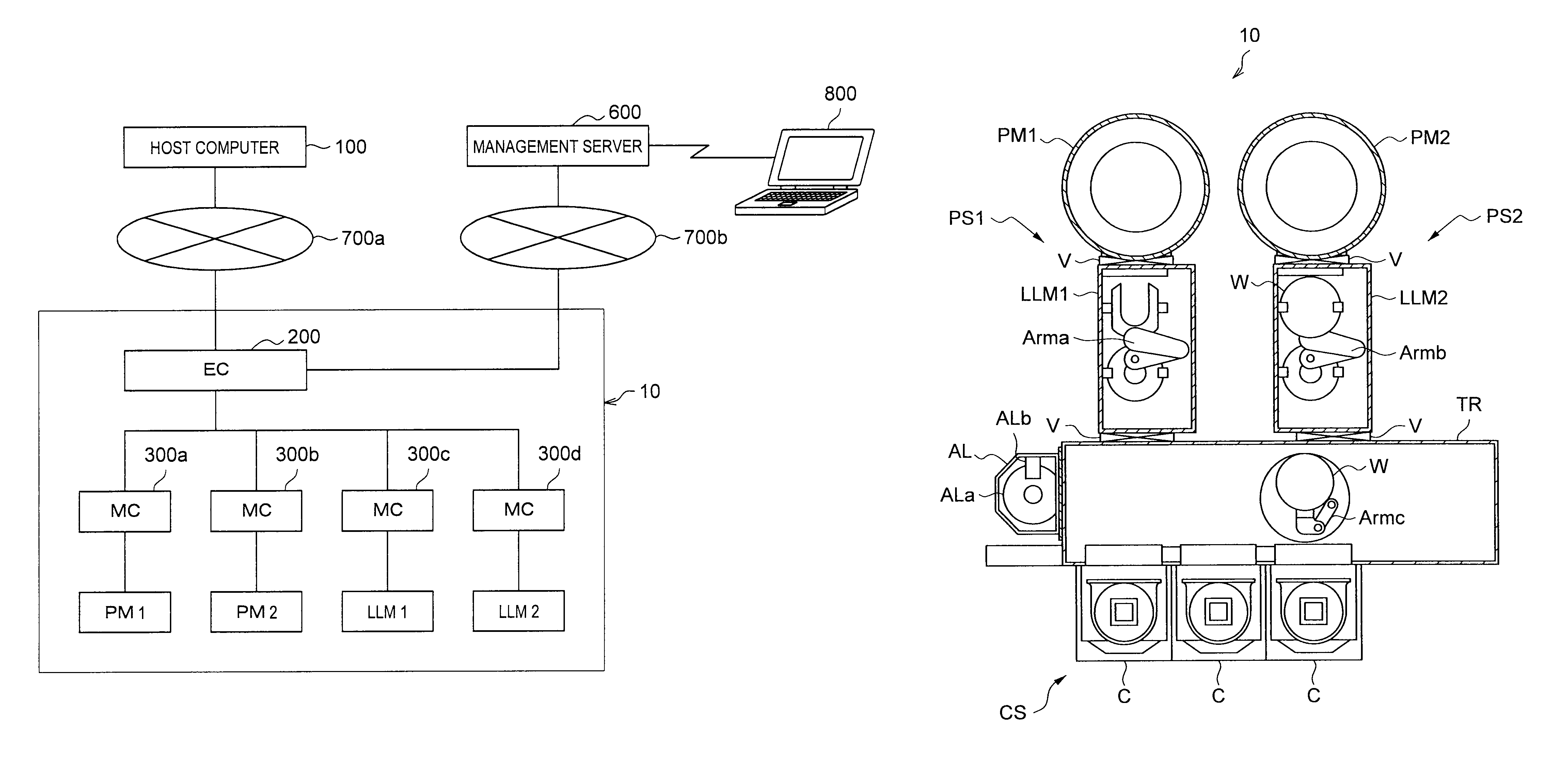
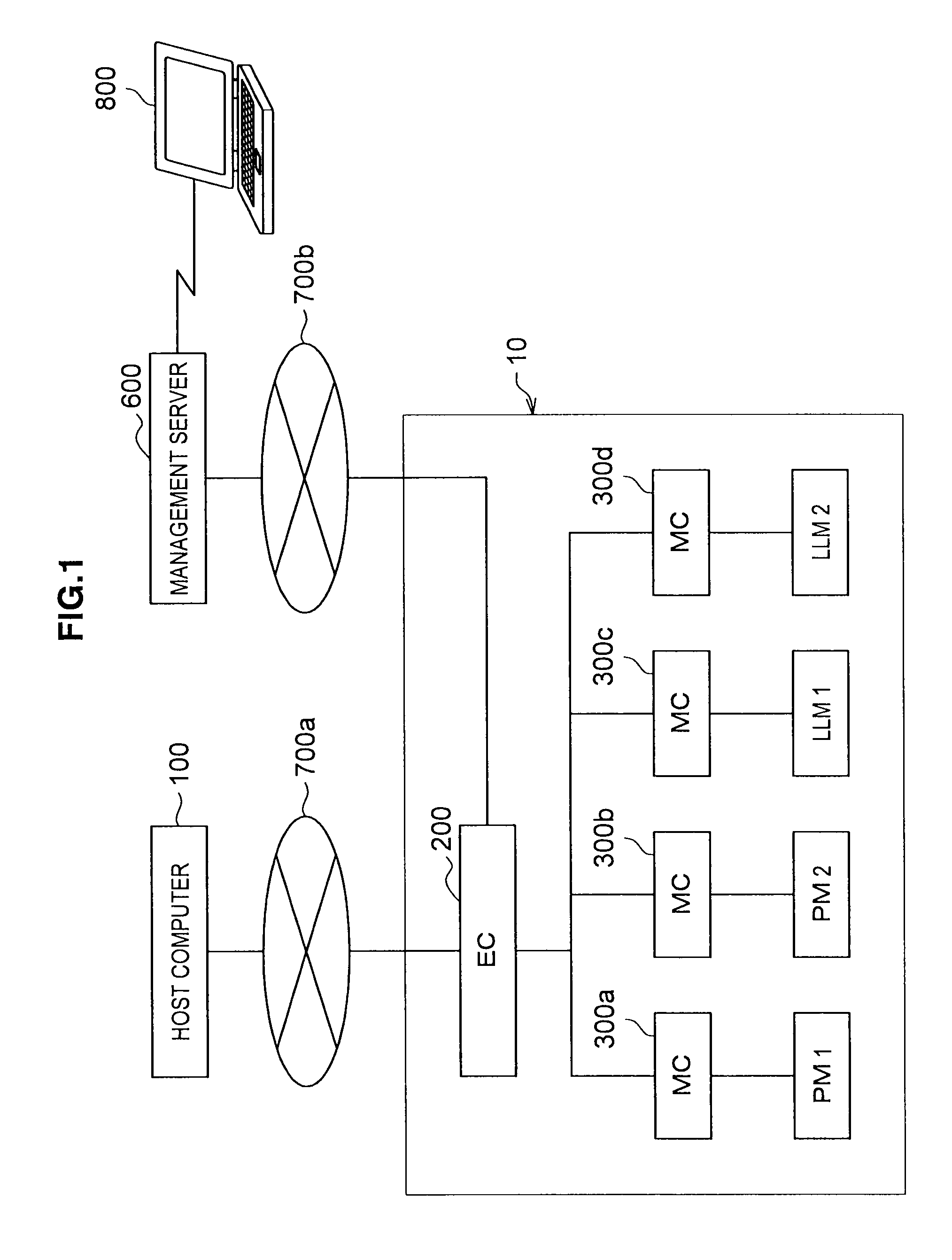
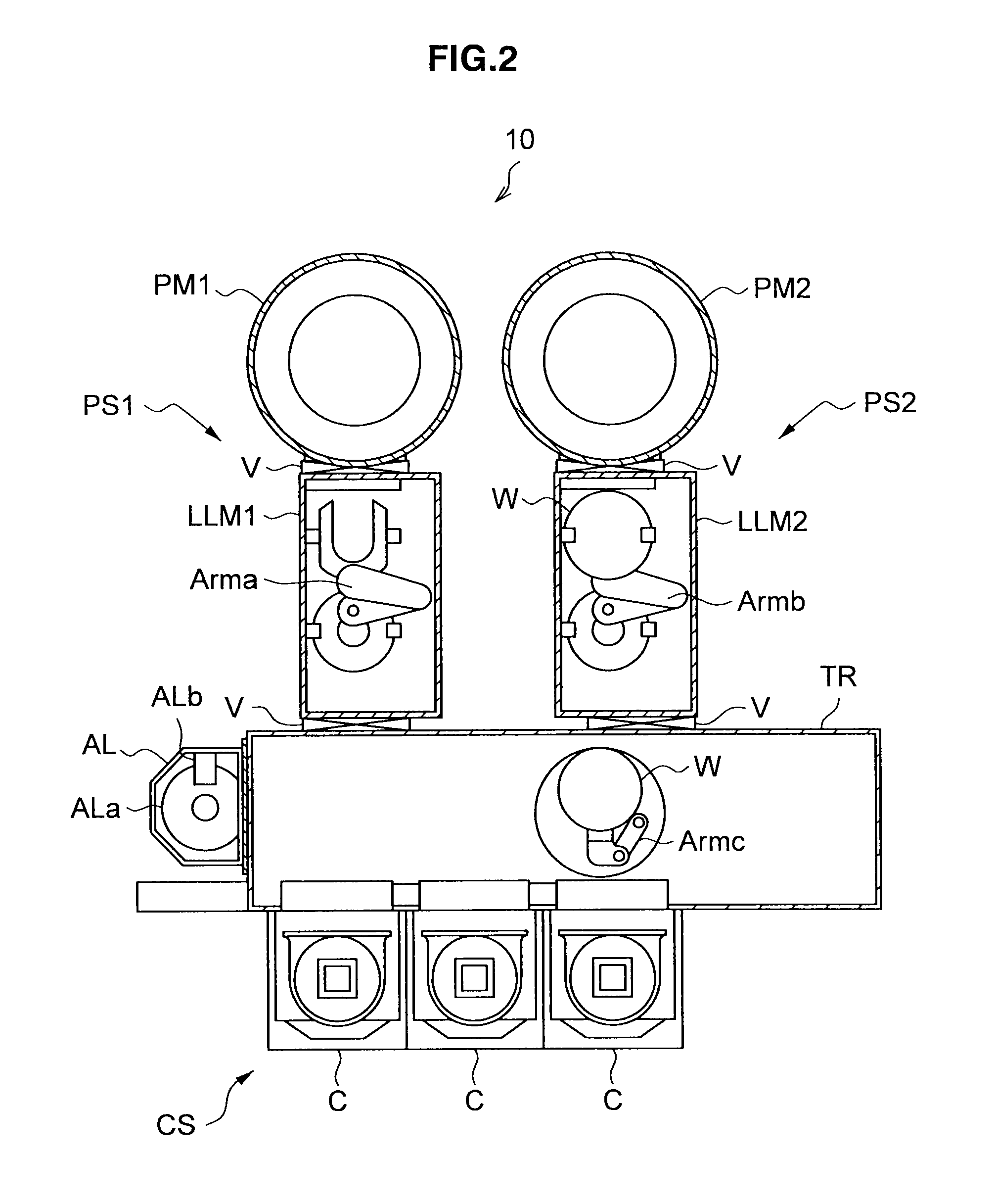
[0146]For example, the processing system 10 that performs the above-described transfer process (FIG. 5), wafer process (FIG. 6) and interrupt process at the time of occurrence of abnormality (FIG. 7) may have a configuration as shown in FIG. 10. The processing system 10 includes cassette chambers (C / C) 400u1, 400u2, a transfer chamber (T / C) 400u3, a pre-alignment (P / A) 400u4, and processing chambers (P / C) (=PM) 400u5, 400u6.

[0147]The C / C 400u1, 400u2 store wafers to be unprocessed and processed wafers, as well as cleaning wafers and lot stabilizing dummy wafers. The P / A 400u4 performs positioning of the wafer W.

[0148]The T / C 400u3 is provided with an articulated arm 400u31 that can bend, stretch and turn. The arm 400u31 has an end provided with a fork 400u32 on which a wafer is held, and transfers the wafer between the C / C 400u1, 400u2, the P / A 400u4, and the P / C 400u5, 400u6, while bending, stretching and turning as necessary.

[0149]With the above confi...

second modified example

[0150 of the Processing System

[0151]Further, the processing system 10 of the present invention may have a configuration as shown in FIG. 11. The processing system 10 includes a transfer system H that transfers the wafer W, and a processing system S that performs a process such as a deposition process or an etching process on the wafer W. The transfer system H and the processing system S are connected via LLM 400t1, 400t2.

[0152]The transfer system H includes a cassette stage 400H1 and a transfer stage 400H2. The cassette stage 400H1 is provided with a cassette case susceptor H1a. Four cassette cases H1b1 to H1b4 are placed on the cassette case susceptor H1a. Each cassette case H1b stores the wafers W to be unprocessed, processed wafers, and wafers for dummy process used for cleaning and seasoning in a multiple levels.

[0153]Two transfer arms H2a1, H2a2 that can bend, stretch and turn are supported by the transfer stage 400H2 such that the transfer arms H2a1, H2a2 slide when they are m...


PUM


Abstract

A processing system includes process modules, load lock modules, an equipment controller, and a machine controller. The equipment controller controls transfer and processing of wafers in the processing system. A transfer destination determining portion determines the transfer destination of each wafer such that each wafer is sequentially transferred to a normally operating process module. When an abnormality occurs in a process module, an evacuation portion temporarily evacuates to a cassette stage the wafer determined is to be transferred to the abnormal process module and that has not yet been transferred to the abnormal process module. When a new transfer destination of the evacuated wafer is determined, if a process that is performed immediately before processing the evacuated wafer in the processing module as the new transfer destination satisfies a predetermined condition, a transfer inhibition portion inhibits the transfer of the evacuated wafer to the new transfer destination.

Description

CROSS REFERENCES TO RELATED APPLICATIONS[0001]The present invention contains subject matter related to Japanese Patent Application JP 2007-241537 filed in the Japan Patent Office on Sep. 18, 2007 and Provisional Application No. 60 / 991,810, filed on Dec. 3, 2007, the entire contents of which being incorporated herein by reference.BACKGROUND OF THE INVENTION[0002]1. Field of the Invention[0003]The present invention relates to a control device for a processing system that performs a predetermined process on an object to be processed, a control method for the processing system, and a storage medium that stores a processing program. More specifically, the present invention relates to a method for controlling transfer of an object to be processed.[0004]2. Description of the Related Art[0005]In recent years, most processing systems provided in semiconductor plants include a transfer mechanism that transfers objects to be processed, and two or more processing chambers in which a predetermin...

Claims


Application Information

Patent Timeline
Patent Type & Authority Patents(United States)
IPC IPC(8): G06F19/00G06F7/00
CPCG05B19/4184G05B2219/31355H01L21/67276G05B2219/32297G05B2219/45031G05B2219/32243Y02P90/02H01L21/02
Inventor NUMAKURA, MASAHIRO
Owner TOKYO ELECTRON LTD
Why Eureka
Try Eureka