Pipe connector device

Active Publication Date: 2011-11-15
OIL STATES INDS UK
View PDF22 Cites 27 Cited by
  • Summary
  • Abstract
  • Description
  • Claims
  • Application Information

AI Technical Summary

Benefits of technology

[0009]According to one aspect of the present invention, there is provided a pipe connector comprising a tubular pin member having a generally frustoconical outer peripheral surface and a tubular box member having a generally frustoconical inner peripheral surface corresponding to the frustoconical outer peripheral surface of the pin member and which overlies the frustoconical surface of the pin member when the members are fully engaged together, the members being provided with inter-engageable annular projections and grooves on the said peripheral surfaces for axially locking the members together when they are fully engaged together, the projections and grooves being spaced apart along the surfaces, means for supplying hydraulic fluid under pressure between the over

Problems solved by technology

In doing this, there is a risk that the projections and grooves may inter-engage before the members are fully telescoped together and it may then prove impossible to disengage the projections and grooves.
These prior art connectors have the problem, however, that when disengaging the members using pressurised hydraulic fluid, to ensure that the projections and grooves at the end of the surfaces of the members overcome the radial restrain and disengage completely, the radial loading imposed by the pressurised fluid on the central portion of the surfaces of the members is substantially greater than is needed to disengage the projections and grooves in these sections.
This can result in the elastic limit of the material

Method used


Image

  • Pipe connector device
  • Pipe connector device
  • Pipe connector device

Examples


Embodiment Construction

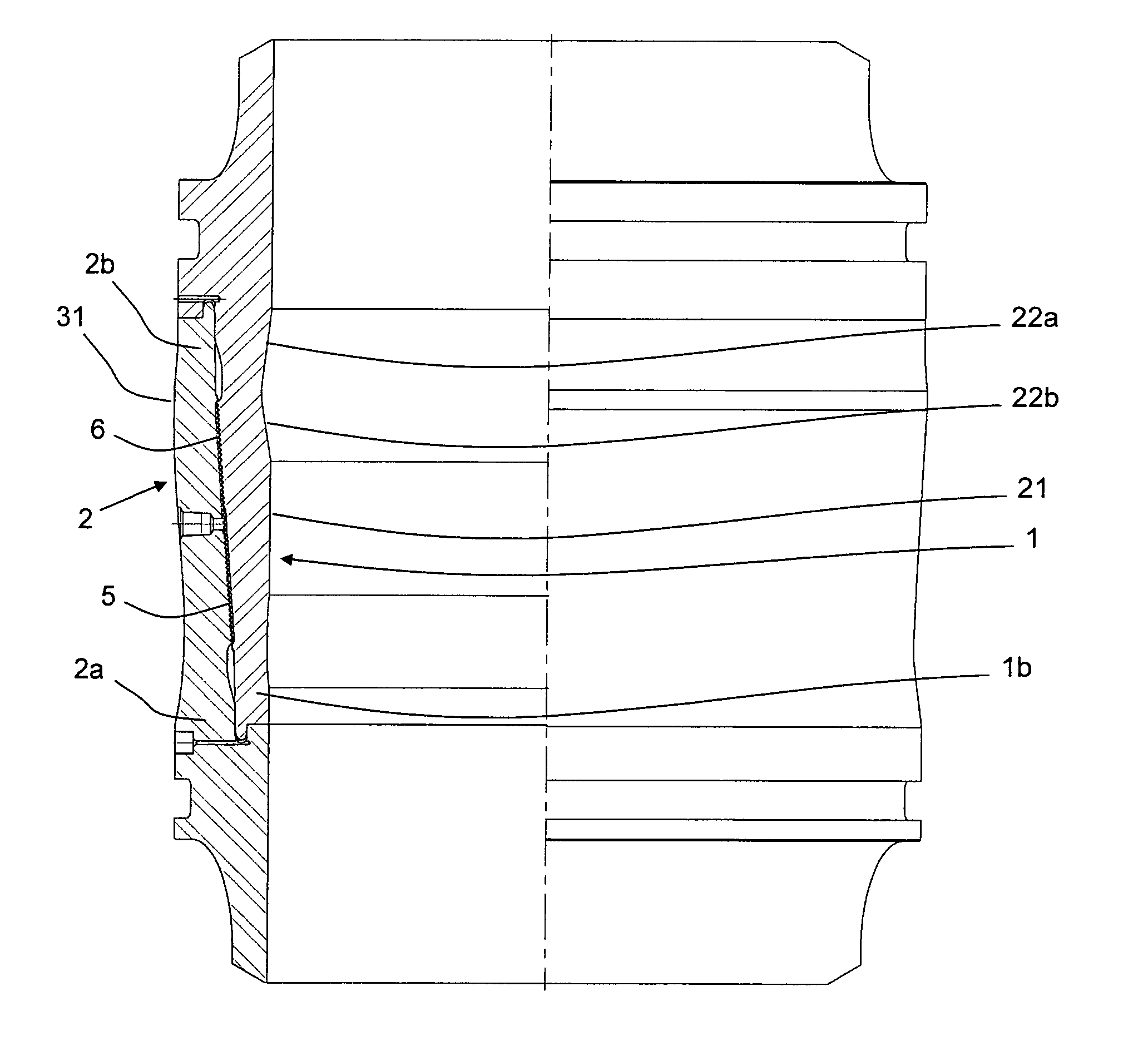
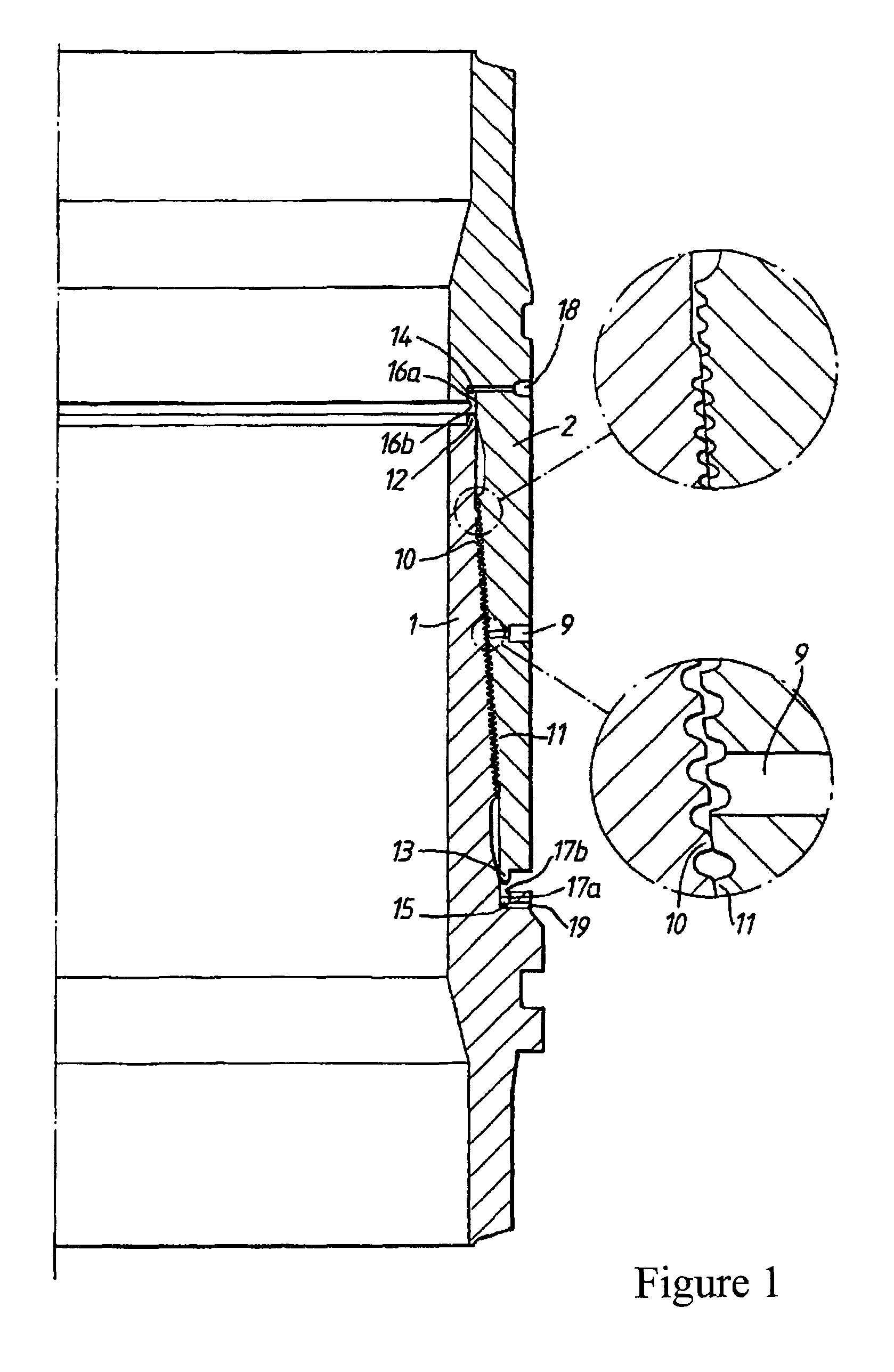
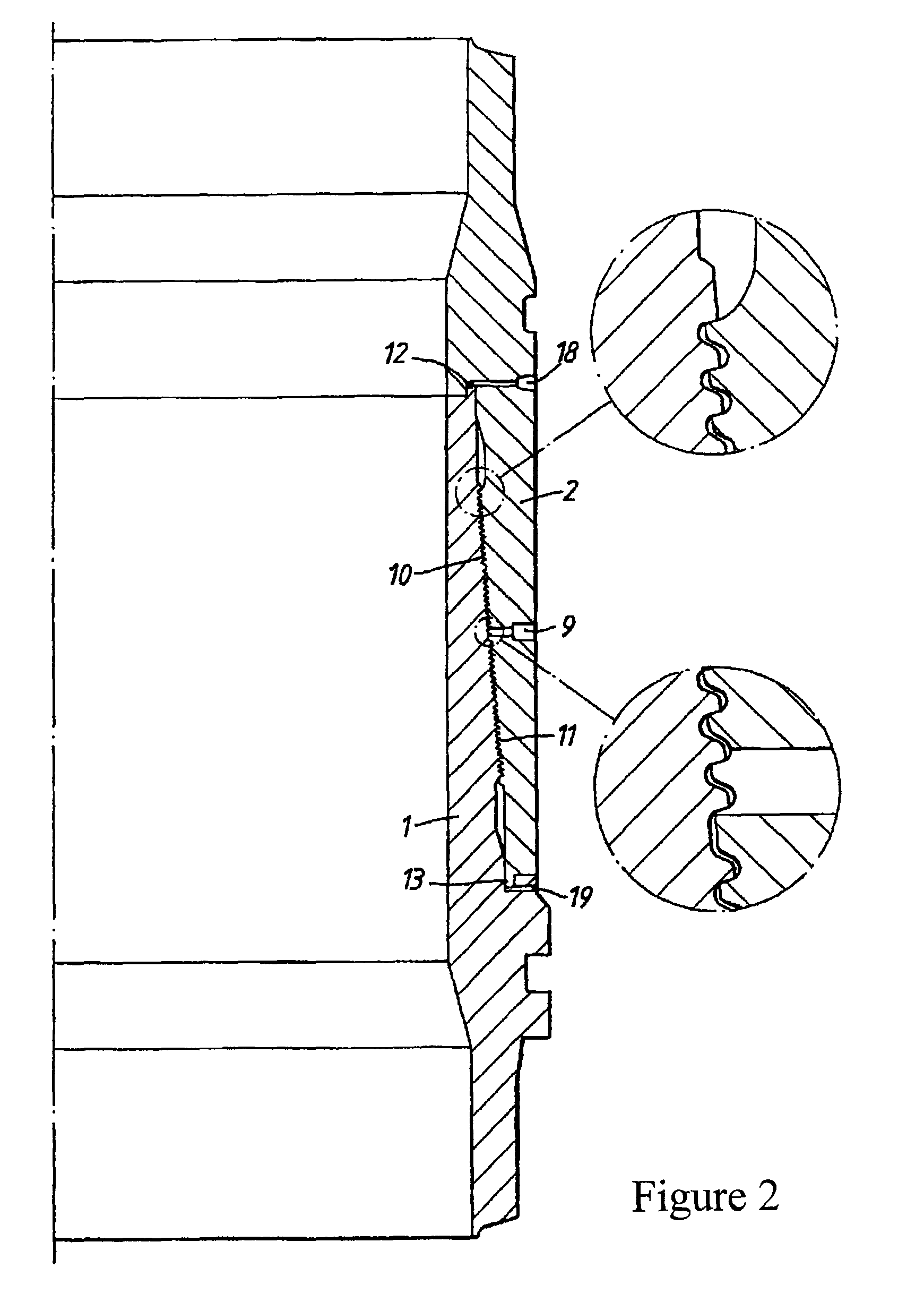
[0023]Referring first to FIGS. 1 and 2, there is shown a prior art pipe connector comprising a tubular pin member 1 and a tubular box member 2, which are connected, or to be connected e.g. by welding, to the ends of two pipes. The members are designed to be telescoped together, the outer surface 3 of the pin member 1 and the inner surface 4 of the box member 2 being both generally frustoconical and provided with complementary annular projections 5 and grooves 6 which are axially spaced apart along the lengths of the surfaces intermediate the ends of the surfaces. The projections and grooves are relatively dimensioned so that, when the members are fully engaged together, corresponding ones of the projections inter-engage in the grooves to axially lock the members together. Pin member 1 is described herein as having projections 5 and box member 2 as having grooves 6, but it will be understood that these descriptions can be reversed.

[0024]Engagement of the members takes place in two st...


PUM


Abstract

A pipe connector comprises a tubular pin member having a frustoconical outer surface and a tubular box member having a frustoconical inner surface corresponding to the outer surface of the pin member and which overlies the frustoconical surface of the pin member when the members are fully engaged. The members are provided with inter-engageable annular projections and grooves on the said peripheral surfaces for axially locking the members together when they are fully engaged together. The projections and grooves are spaced apart along the surfaces. The inner tubular surface of the pin member and an outer tubular surface of the box member each include at least one of a recess and/or a protrusion/radially enlarged section which reduces and/or increases the thickness of the tubular wall along the length of the associated member so as to balance the displacement of the members at different points along the length thereof under injection pressure.

Description

CROSS-REFERENCE TO RELATED APPLICATIONS[0001]This application is a National Stage of International Patent Application No. PCT / GB2009 / 001341, filed on May 28, 2009, which claims priority to foreign Patent Application No. GB 0811846.5, filed on Jun. 27, 2008, the disclosures of which are incorporated herein by reference in their entirety.FIELD OF THE INVENTION[0002]The present invention relates to improvements in pipe connectors particularly but not exclusively for use in the oil industry for connecting metal pipe sections of pipe strings.BACKGROUND OF THE INVENTION[0003]So called Merlin type pipe connectors are well known in the art for connecting pipes together and are disclosed in GB1573945, GB2033518, GB2099529, GB2113335 and GB2138089. The connection is formed by tubular pin member having a frustoconical outer peripheral surface and a tubular box member having a generally frustoconical inner peripheral surface corresponding to the frustoconical outer peripheral surface of the pin...

Claims


Application Information

Patent Timeline
IPC IPC(8): F16L25/00
CPCE21B17/046F16L37/62
Inventor MORGAN, DAVID JAMES EDWARDSINCLAIR, DAVID MALCOLM
Owner OIL STATES INDS UK
Why Eureka
Try Eureka