Dental implant, abutment structure and method for implanting a dental implant

a technology of dental implants and abutments, applied in dentistry, dental prosthetics, medical science, etc., can solve the problems of difficult and costly production points, strength to withstand, and difficulty in achieving from a production point, and achieve the effect of increasing the retention capability of said abutment parts, increasing the retention capability, or frictional, and increasing the retention capacity

Inactive Publication Date: 2011-11-15
ASTRA TECH SE
View PDF23 Cites 4 Cited by
  • Summary
  • Abstract
  • Description
  • Claims
  • Application Information

AI Technical Summary

Benefits of technology

[0024]At least one notch at the drive means may be a beneficial arrangement for enabling the tightening or removal of the abutment screw from the dental implant. It may also be suitable to provide the drive means with two notches. The notches may be arranged at the coronal end surface of the abutment screw and they may be perpendicular in relation to each other and intersecting each other. This arrangement may even further assist a user in tightening and removing of the abutment screw to and from the fixture of the dental implant.
[0126]An abutment screw may be made as a solid piece. As a consequence of this, the above-mentioned problems with thin wall thickness of the part supporting the coronal component may be at least partly reduced. The strength of the abutment screw may therefore be satisfactorily high even when the diameter of the abutment screw, and hence the abutment structure, is rather small in comparison to its height.

Problems solved by technology

With concern taken to the desired height of the abutment structure, this may be difficult and costly to achieve from a production point of view.
Furthermore, the dental implant and the abutment structure of the dental implant may be subject to forces, that they must have the strength to withstand.

Method used


Image

  • Dental implant, abutment structure and method for implanting a dental implant
  • Dental implant, abutment structure and method for implanting a dental implant

Examples


Embodiment Construction

[0132]The inventive concept relates to dental implants, abutment structures and methods for implantation of a dental implant.

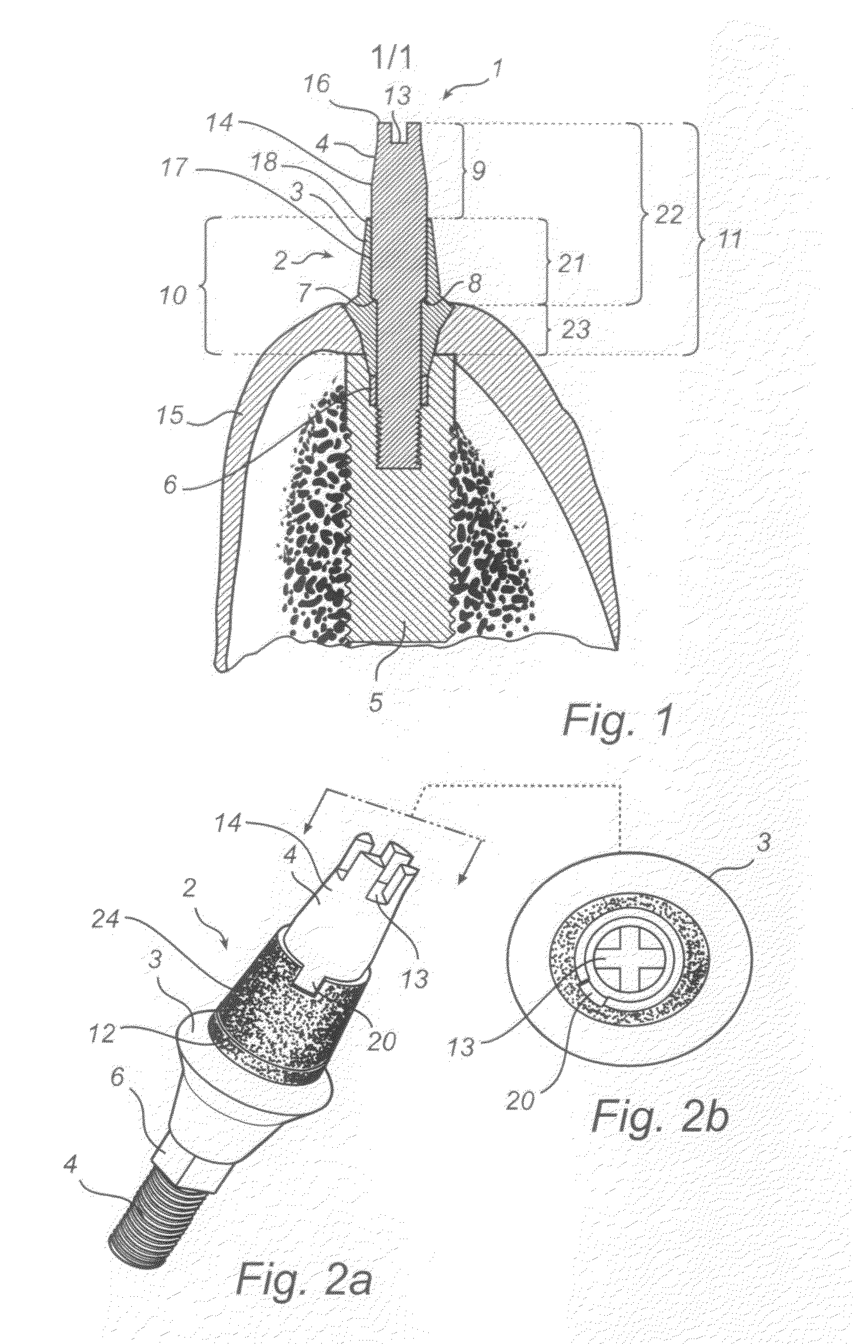
[0133]An embodiment of the inventive concept will now be described in relation to FIGS. 1 to 2b.

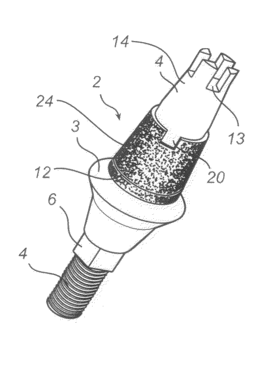
[0134]The implant 1 is a dental implant for implantation into a maxilla or mandible of a patient and it is adapted to support a coronal component such as a crown, a part of a dental bridge, a burn-out cylinder, a healing cap, a waxing sleeve or an impression pick-up.

[0135]The dental implant 1 comprises a fixture part 5 having a generally cylindrical shape. The length of the fixture part is preferably between 6-19 mm and the maximum width around 3-6 mm. The fixture part 5 is adapted for insertion into a bore hole drilled in the bone tissue of a maxilla or a mandible. The fixture 5 is made from commercially pure titanium, a titanium alloy, another biocompatible metal or metal alloy or a ceramic to promote osseointegration of the implant with the bone tissue of the bo...


PUM


Abstract

At least one embodiment of the present invention relates to a dental implant for supporting a coronal component. In at least one embodiment, the implant includes a fixture part forming an apical bone contact part of the implant, an abutment part forming a coronal component support part of the implant, and an abutment screw, wherein said abutment part is arranged to, in an assembled state of said dental implant, be fixed to the fixture part by the abutment screw, and wherein a coronal end portion of the abutment screw is arranged to, in the assembled state, be positioned coronally of a coronal end portion of the abutment part. At least one embodiment of the present invention also relates to abutment structures and methods for implanting a dental implant.

Description

TECHNICAL FIELD OF THE INVENTION[0001]The present invention relates to a dental implant for supporting a coronal component, said implant comprising a fixture part forming an apical bone contact part of said implant, an abutment part forming a coronal component support part of said implant, and an abutment screw, wherein said abutment part is arranged to, in an assembled state of said dental implant, be fixed to said fixture part by said abutment screw.[0002]The present invention also relates to an abutment structure for use in a dental implant adapted to support a coronal component, wherein said abutment structure is adapted to be supported by a fixture part of said implant, said abutment structure comprises at least an abutment part and an abutment screw, wherein said abutment part is adapted to be fixed to said fixture part by said abutment screw.[0003]The present invention also relates to a method for implanting a dental implant.BACKGROUND ART[0004]Dental implant systems are wide...

Claims


Application Information

Patent Timeline
Patent Type & Authority Patents(United States)
IPC IPC(8): A61C8/00
CPCA61C8/005A61C8/0069A61C8/006A61C8/00
Inventor ENGSTROM, KENTHALLDIN, ANDERS
Owner ASTRA TECH SE
Why Eureka
Try Eureka