Control device for automatic transmission

a control device and automatic transmission technology, applied in the direction of motor/generator/converter stopper, process and machine control, etc., can solve the problems of unstable driving power transmitted to the wheels, unstable traveling state of the vehicle, unstable driving power transmitted from the engine to the gear mechanism, etc., to improve the control precision of current feedback of the motor, high precision, and secure the effect of vehicle safety

Active Publication Date: 2011-11-15
MITSUBISHI ELECTRIC CORP
View PDF16 Cites 2 Cited by
  • Summary
  • Abstract
  • Description
  • Claims
  • Application Information

AI Technical Summary

Benefits of technology

[0030]The present invention has been implemented to solve the above problems, and has an object to provide a control device for an automatic transmission which can enhance the control precision of current feedback of a motor without slackening variation of a motor current value, and control clutch engaging force with high precision, thereby securing safety of a vehicle and feeling.
[0032]According to the present invention, the engaging force of the clutch can be controlled with high precision by enhancing the current feedback control precision of the motor, and thus the stable travel state of a vehicle can be secured.

Problems solved by technology

Here, when the engaging force of the clutch is unstable, the driving power transmitted from the engine to the gear mechanism becomes unstable, and finally the driving power transmitted to the wheels becomes unstable.
Therefore, this makes the traveling state of the vehicle unstable, and it makes a driver feel uncomfortable.
When the current value is dispersed, a result of current feedback control becomes unstable.
However, in the technique disclosed in JP-A-2004-282969, no attention is paid to a case where the coils of the respective phases of the motor are dispersed in resistance, etc.
Therefore, when current is dispersed and thus the torque amount is also dispersed, the engaging force of the clutch cannot be controlled with high precision.
However, as shown in FIG. 15, when the dispersion of the motor current is reduced by setting K to a smaller value, there occurs a problem that a convergence time required for the current to reach motor target current is increased.
Accordingly, the current feedback control is unstable.
As described above, in the related arts, the feedback control precision is unstable, the current control precision is low and the clutch engaging force cannot be precisely controlled.
Accordingly, the clutch engaging force is unstable, and the travel state of a vehicle is unstable.
However, in this case, the variation of the motor current value is also slackened, and this causes a risk that instantaneous response performance is deteriorated.

Method used


Image

  • Control device for automatic transmission
  • Control device for automatic transmission
  • Control device for automatic transmission

Examples


first embodiment

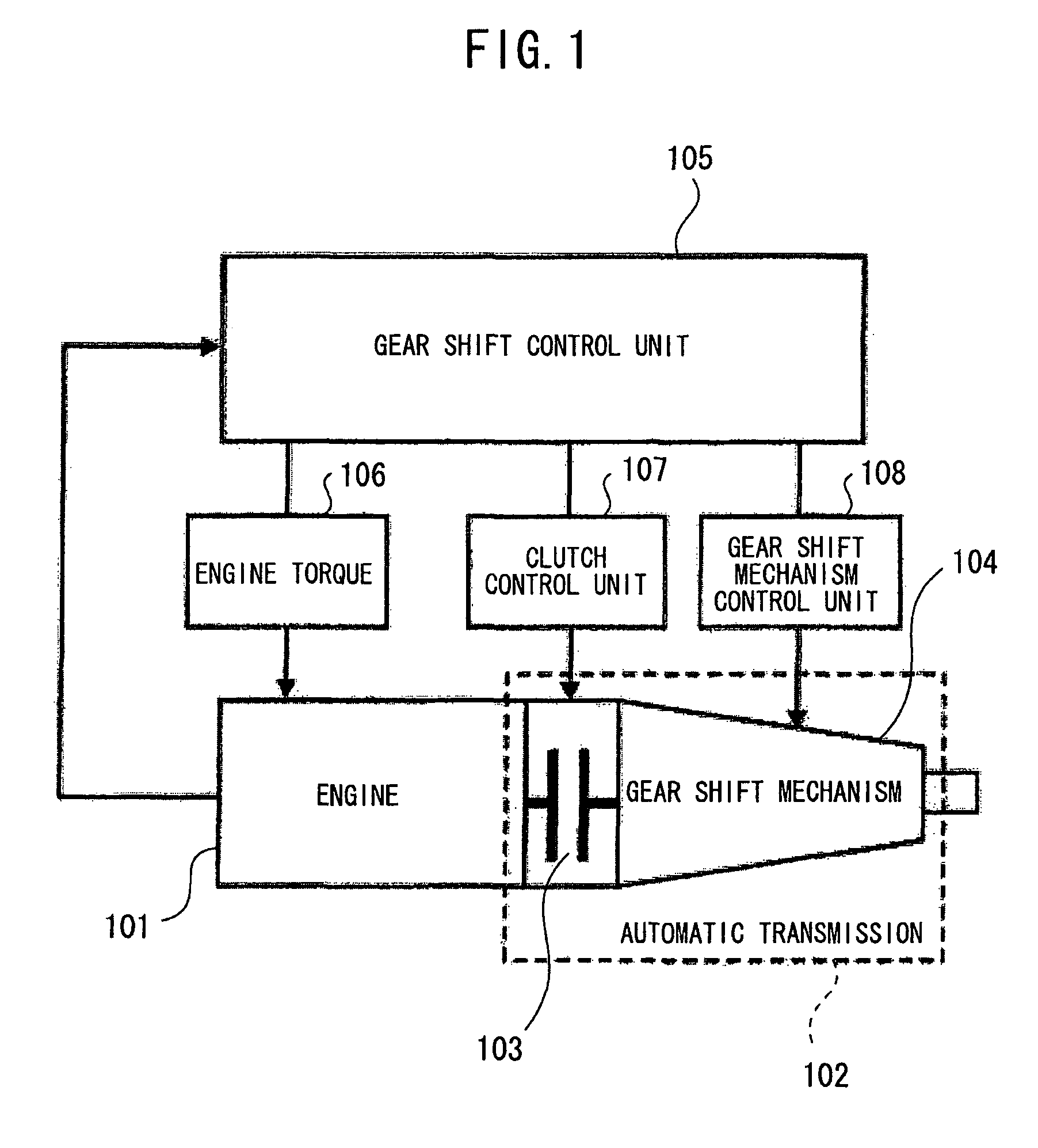
[0050]FIG. 1 is a diagram showing the system construction of an automatic transmission control device according to a first embodiment of the present invention. In FIG. 1, an engine 101 and an automatic transmission 102 are joined to each other by a clutch 103. The clutch 103 is fixed to an input portion of the automatic transmission 102, and transmits driving power from the engine 101 to the automatic transmission 102. The automatic transmission 102 is provided with a gear shift mechanism 104 for changing a shift gear stage of the automatic transmission 102.

[0051]A gear shift control unit 105 controls the shift gear stage of the automatic transmission 102 by engaging the clutch 103 of the automatic transmission 102 and changing the construction of the gear shift mechanism 104. An engine torque control unit 106 controls the torque amount of the engine at the gear shift time on the basis of an instruction of the gear shift control unit 105. A clutch control unit 107 contains a motor c...

second embodiment

[0093]Next, a control device for an automatic transmission according to a second embodiment of the present invention will be described.

[0094]In the first embodiment, the description is made on the embodiment of securing the stability of the motor current when the coil resistance is dispersed among the respective phases of the brushless motor. According to the second embodiment, the current feedback control is performed by using the average value of the detection values of the motor current, whereby the average current of the brushless motor is made to follow a target current to make the average torque of the brushless motor follow a target torque.

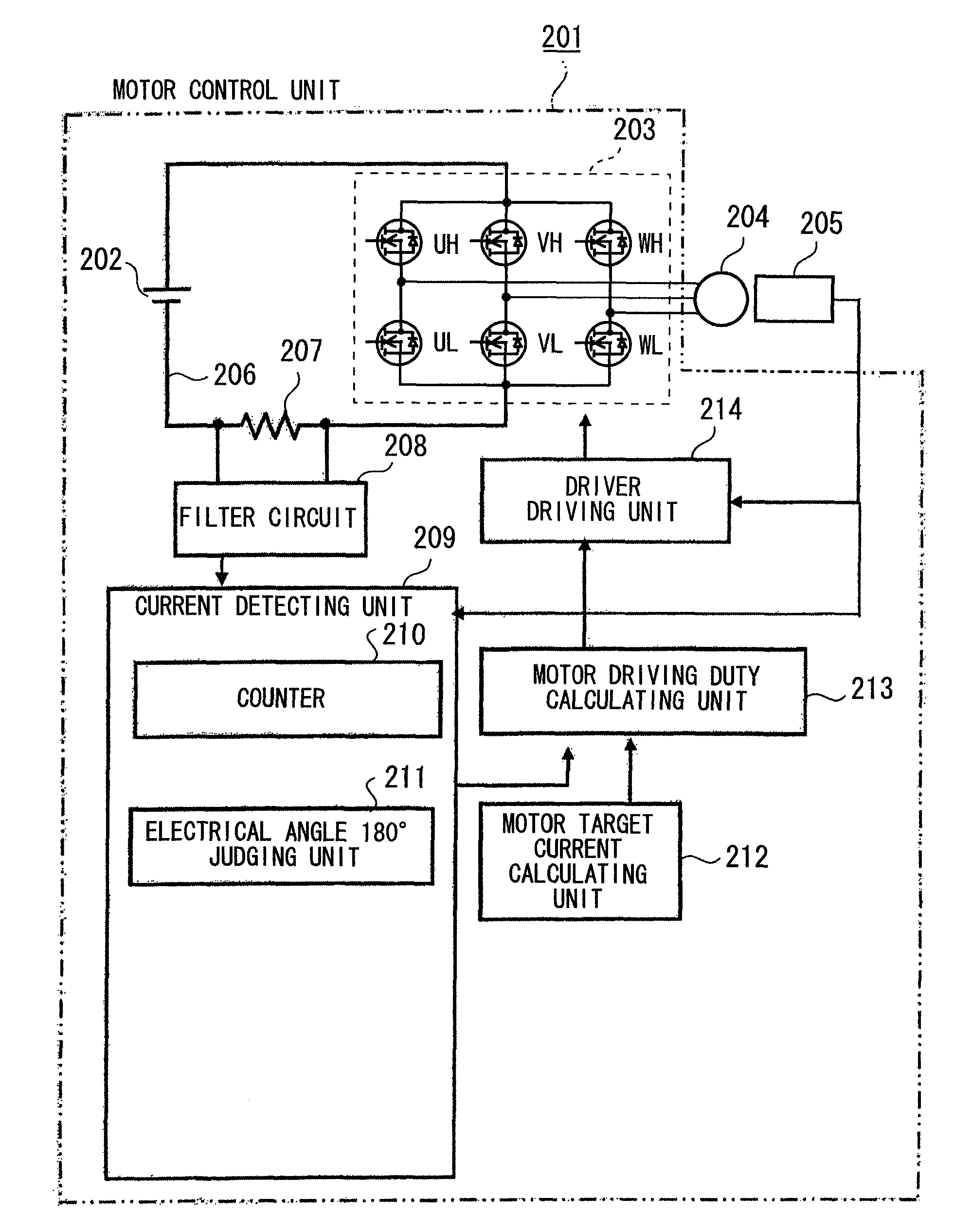
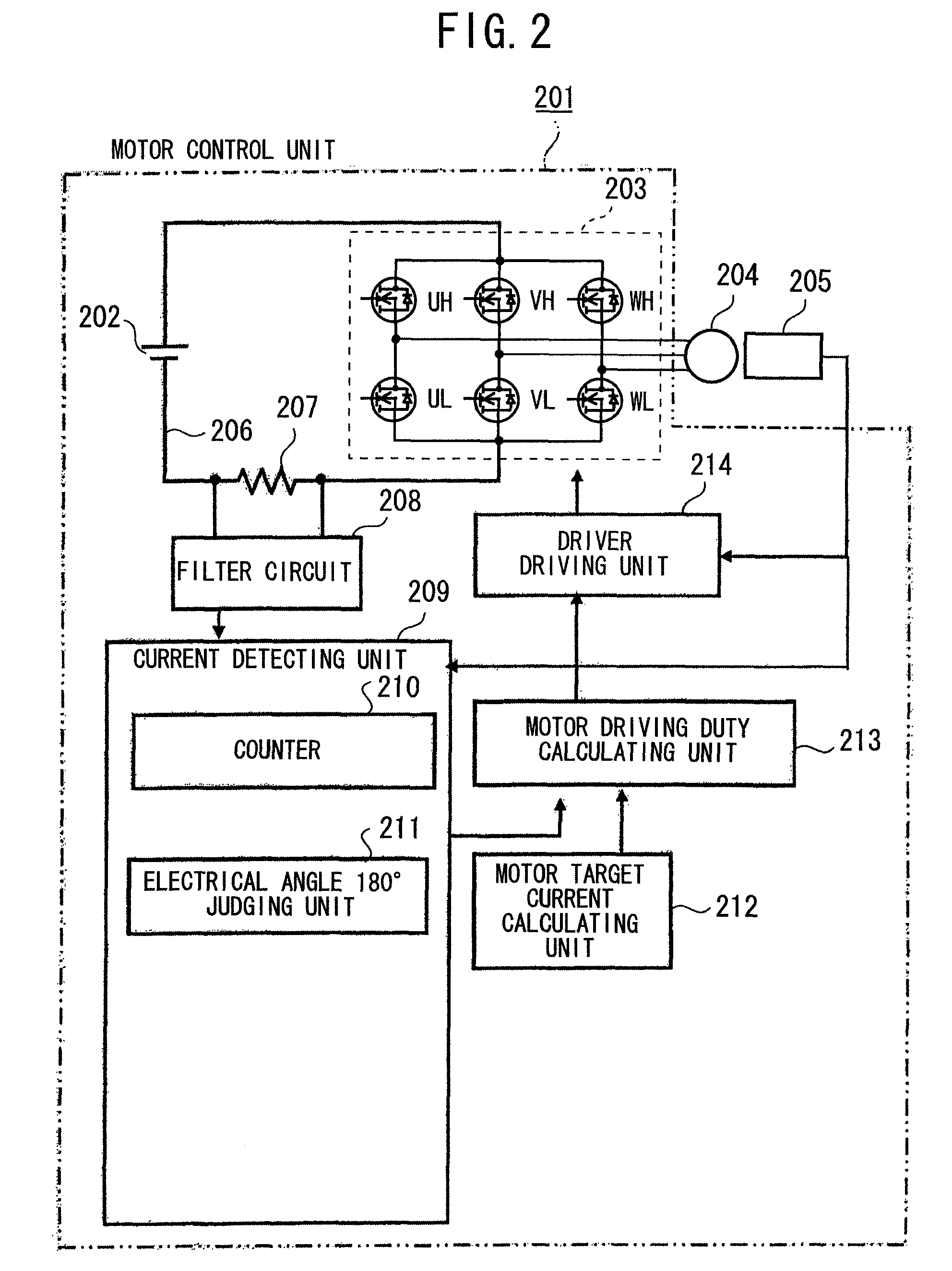
[0095]The control device for the automatic transmission according to the second embodiment uses a current detecting unit 601 shown in FIG. 6 in place of the current detecting unit 209 constituting the motor control unit 201 described in the first embodiment, and the other construction is the same as the first embodiment. In the following de...

third embodiment

[0117]Next, the control device for the automatic transmission according to a third embodiment will be described.

[0118]In the control device for the automatic transmission according to the third embodiment, when the current average value over the electrical angle of 180° is calculated, a current value which is sampled at a detection timing of the latest hall sensor signal variation is set as the latest data, and the current average value is calculated from past three data. That is, a current value which is sampled at a timing at which the latest hall sensor signal variation is detected is set as the latest data, and past three data are stored into the current value storing unit 604 of FIG. 6 described in the second embodiment. Accordingly, the current average value over the electrical angle of 180° can be renewed every 60° in electrical angle, and the following performance when the target current varies can be enhanced. The other construction is the same as the second embodiment, and...


PUM


Abstract

A control device for an automatic transmission includes a current detecting unit for detecting motor current. The current detecting unit has a counter for counting variation number of a rotational position signal output from a rotational position detecting unit for detecting the rotational position of a motor, and an electrical angle 180° judging unit for judging rotation of electrical angle 180° of the motor. A voltage occurring in a current detecting resistor is sampled at a timing of each integral multiple of the electrical angle of 180° judged in the electrical angle 180° judging unit, and rotation of the motor is controlled in accordance with the difference between motor target current calculated in the motor target current calculating unit and motor current.

Description

BACKGROUND OF THE INVENTION[0001]1. Field of the Invention[0002]The present invention relates to a control device for an automatic transmission mounted in a vehicle such as a car or the like, and particularly to an automatic transmission control device for performing gearshift control by using a motor.[0003]2. Description of the Related Art[0004]In general, a vehicle such as a car or the like which has an automatic transmission mounted therein uses an engine as a driving power source, and transmits the driving power generated by the engine through the automatic transmission to wheels, whereby the vehicle can run. A start clutch is provided in the automatic transmission, and when it is necessary to transmit the driving power transmitted from the engine to a gear mechanism, the start clutch is engaged with the gear mechanism. Conversely, when it is unnecessary to transmit the driving power to the gear mechanism, the start clutch is disengaged from the gear mechanism. The control of th...

Claims


Application Information

Patent Timeline
Patent Type & Authority Patents(United States)
IPC IPC(8): G05F1/00G05D1/00G06F7/00H02K29/08B60K1/00B60K17/00F16D48/06H02P6/06H02P6/08H02P6/28
CPCF16D48/064H02P6/085F16D2500/1023F16D2500/3022F16D2500/3026H02P2101/45F16D2500/70673H02P2205/01F16D2500/7042
Inventor OKABE, TAKERUYONEZAWA, SHIROKAMIOKA, NOZOMUSHODA, TOMOHISAHORII, MASAKIOGAWA, YASUFUMIISHIKAWA, OSAMU
Owner MITSUBISHI ELECTRIC CORP
Why Eureka
Try Eureka