
Risk assessment for planned trajectories

a risk assessment and planned trajectories technology, applied in the field of devices and methods for preparing and planning the placement of devices, can solve the problems of increasing the determined level of risk, increasing the risk of inaccurate placement, and increasing the respective level of risk, so as to reduce the rate of delivery or injection pressure

Active Publication Date: 2011-11-15
BRAINLAB
View PDF13 Cites 28 Cited by
  • Summary
  • Abstract
  • Description
  • Claims
  • Application Information

AI Technical Summary

Benefits of technology

[0014]The three dimensional structure of the body or tissue can be considered and inaccuracies of the planning and placement approach, which may result, for example, from restricted image resolution, non-perfect patient registration, instability or flexibility of a catheter and so on, can be determined or anticipated for consideration. Then, the risk of reaching or not reaching a specific structure can be rated. For example, it can be considered that a catheter having a high flexibility may be deflected to cross a critical region, which may increase the determined level of risk. Furthermore, it can be easy to stay away from a critical area, such as a sulcus, by a predetermined distance of 5 mm at the point of entry, whereas further down the trajectory, e.g., in the body or patient, the predetermined distance of 5 mm is insufficient if an unstable catheter is used (e.g., a catheter that is likely to bend toward the risk structure).
[0029]The method described herein enables the physician to focus on finding the optimal trajectory for a treatment or medical examination by providing information in terms of anatomical, functional and / or physiological information and / or based on warnings about the potential adverse effects when chosen trajectories cross a critical area or region as outlined. Transferring the information to a surgical navigation system increases safety for the patient by excluding areas associated with high-risk levels.

Problems solved by technology

For example, it can be considered that a catheter having a high flexibility may be deflected to cross a critical region, which may increase the determined level of risk.
Also, if the holding device is fixed far away from the entry point, the risk of inaccurate placement is elevated versus fixing the holding device close to the entry point.
A catheter having a high flexibility may be deflected into or towards a structure of risk, which would increase the respective level of risk, whereas a stiff or hard catheter may decrease this level of risk.
However, in vascular structures, the stiff catheter may increase the risk of harming vascular structures compared to a more flexible catheter.
Also, an experienced or a good surgeon may decrease the calculated level of risk, whereas an inexperienced surgeon may increase it.

Method used


Image

  • Risk assessment for planned trajectories
  • Risk assessment for planned trajectories
  • Risk assessment for planned trajectories

Examples


Embodiment Construction

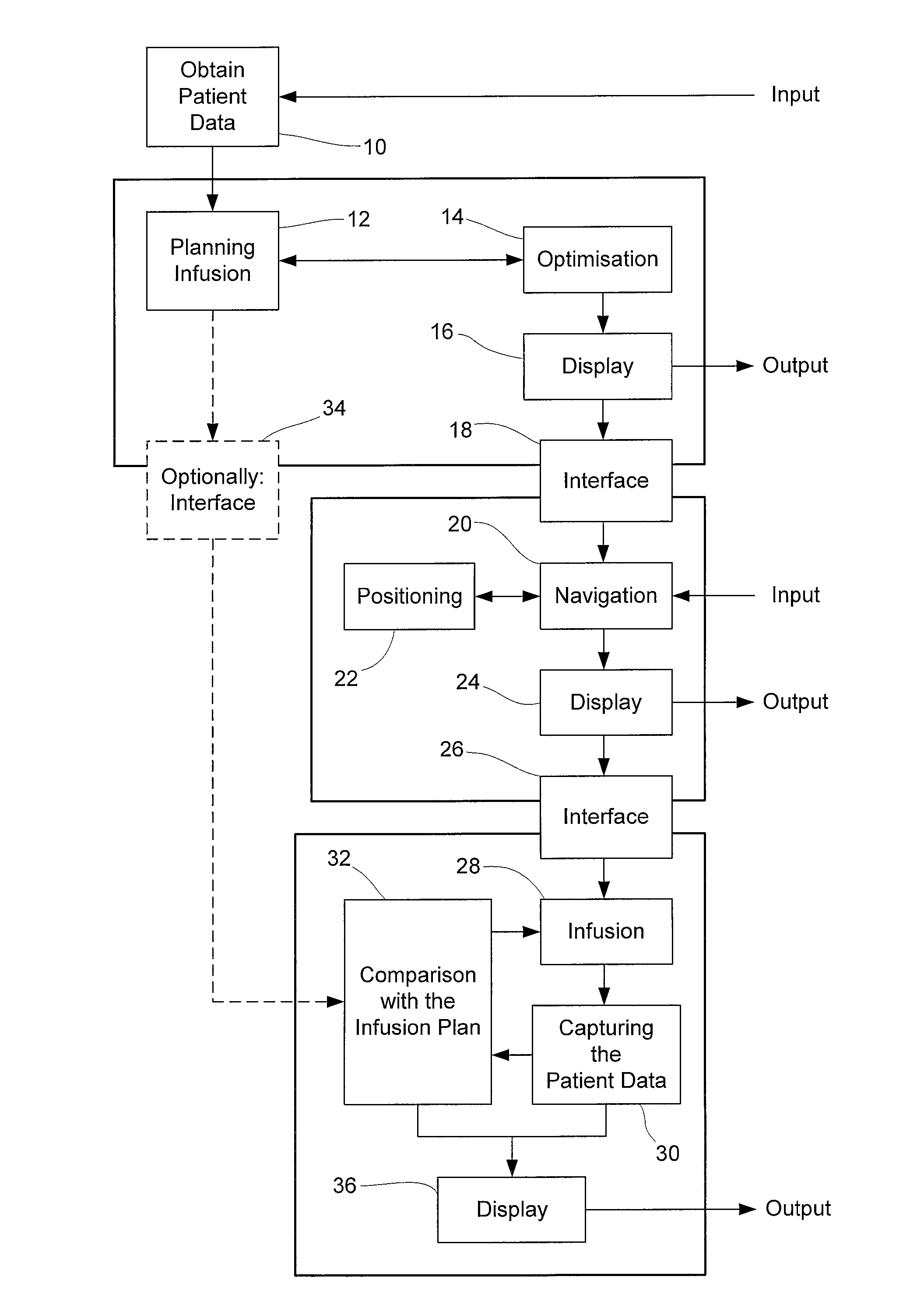
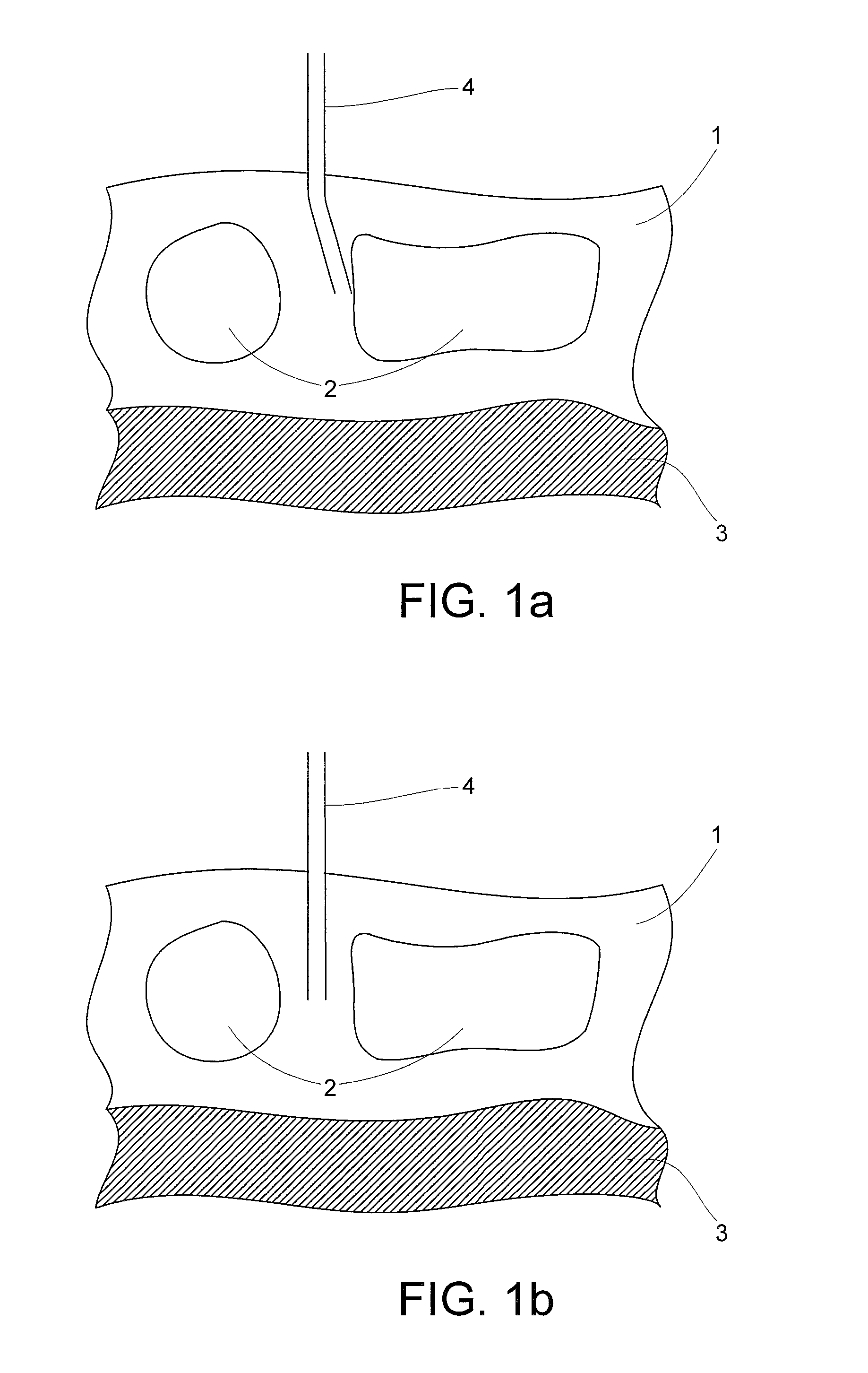
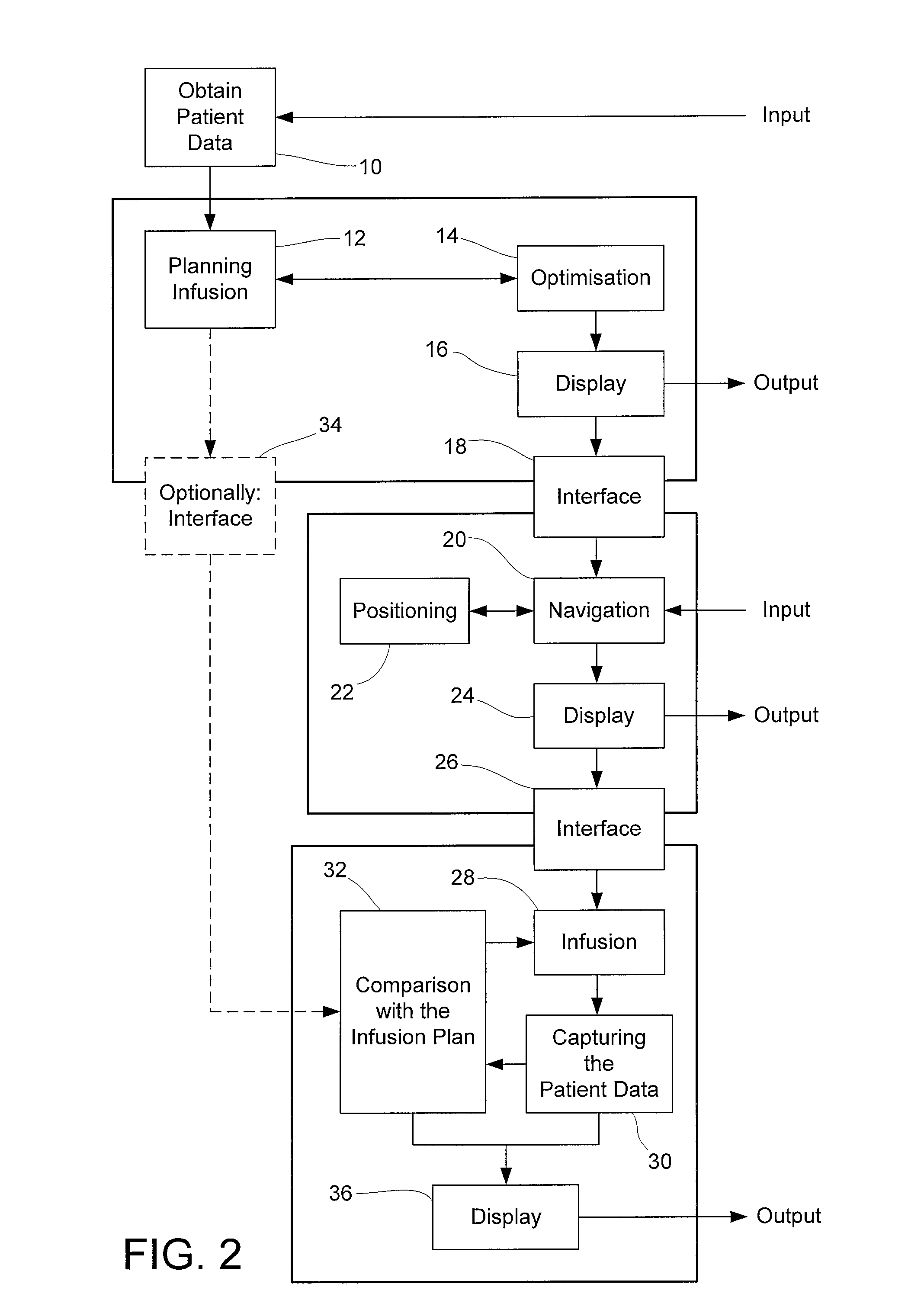
[0058]FIG. 1a shows an image acquired using an exemplary method for planning the movement and placement of a catheter 4 in tissue 1 of a patient. The patient 1 has structures of risk 2, e.g., damageable regions, and a target region 3, e.g. a region to be treated, such as a tumor. For efficiently treating the tumor 3, it is desirable to position the catheter 4 as near as possible to the tumor 3 or directly into the tumor 3 so that the treatment substance can be directly injected into the tumor. The remainder of the tissue should not come into contact with the substance. Further, the catheter 4 should not cross the structures of risks 2 and should not be placed in close proximity to the structures of risk 2. For this purpose, an ultrasound imaging system can be used to image and display the tissue 1, as shown in FIG. 1a, so that the movement and placement of the catheter 4 can be planned and controlled. As shown in FIG. 1a, a catheter 4 is inserted into the tissue 1 at a position susp...


PUM


Abstract

A method for planning the placement of a device in a body includes analyzing information of at least part of the internal structure of the body of a patient to determine if at least one specific or critical region or structure lies within a region of interest, said region of interest within a predetermined distance of the planned trajectory of the device in the body. Then, a level of risk is assessed to the at least one specific or critical region or structure that is within the region of interest.

Description

RELATED APPLICATION DATA[0001]This application claims priority of U.S. Provisional Application No. 60 / 746,182 filed on May 2, 2006, which is incorporated herein by reference in its entirety.FIELD OF THE INVENTION[0002]The present invention relates to device and method for preparing and planning the placement of devices, such as, for example, biopsy needles, stimulators, probes or catheters, including intra-cranial catheters, in a body. More particularly, the invention relates to carrying out an infusion, drainage of a substance, such as fluid, into or out of tissue, or biopsies, preferably after having prepared and planned the placement of the device.BACKGROUND OF THE INVENTION[0003]In general, the term “infusion” is understood as any administration of a liquid or solid substance and / or an infusing medium, such as pharmaceutical substances, cells, genes, enzymes, proteins, liposomes, antibodies, hormones, viral vectors, viruses or the like. The substance may be introduced directly i...

Claims


Application Information

Patent Timeline
Patent Type & Authority Patents(United States)
IPC IPC(8): A61B17/52A61F5/00A61M21/00G16Z99/00
CPCA61B19/201A61B19/52A61B19/5244G06F19/321G06F19/3406G06F19/3431G06F19/3437A61B19/50A61B2019/507A61B2019/5255A61B2019/566A61M2005/14292A61B90/36A61B2034/2055A61B2034/256A61B34/20A61B90/11A61B34/10A61B2034/107G16H40/63G16H50/30G16H50/50G16H20/40G16H30/20G16Z99/00
Inventor RODRIGUEZ PONCE, MARIA INMACULADAPEDAIN, CHRISTOPHHARTLEP, ANDREAS
Owner BRAINLAB
Learn More