
Method and device for receiving OPFDM-DQPSK signal

a technology of opfdm-dqpsk signal and receiving device, which is applied in the field of communication, can solve problems such as data error recovery, and achieve the effects of reducing crosstalk, enhancing the receiving performance of the receiving device, and reducing the number of errors

Active Publication Date: 2011-11-22
HUAWEI TECH CO LTD
View PDF7 Cites 7 Cited by
  • Summary
  • Abstract
  • Description
  • Claims
  • Application Information

AI Technical Summary

Benefits of technology

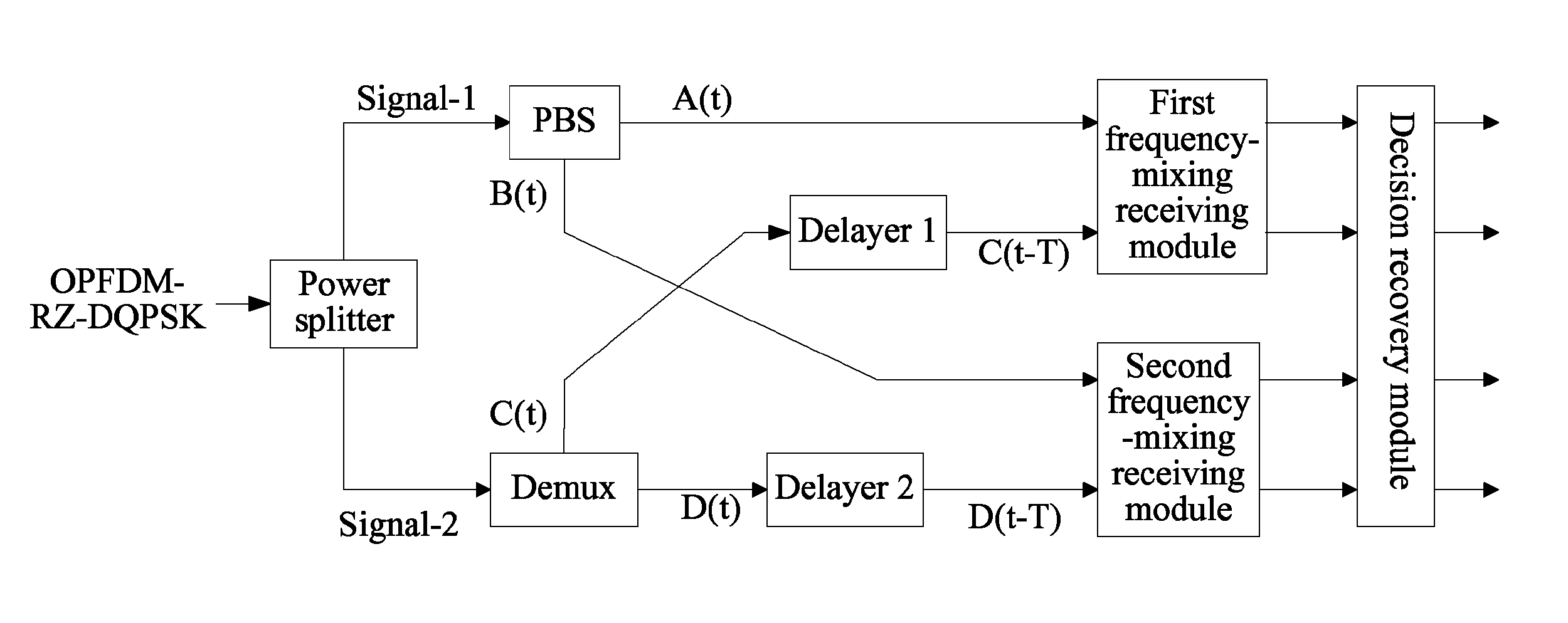
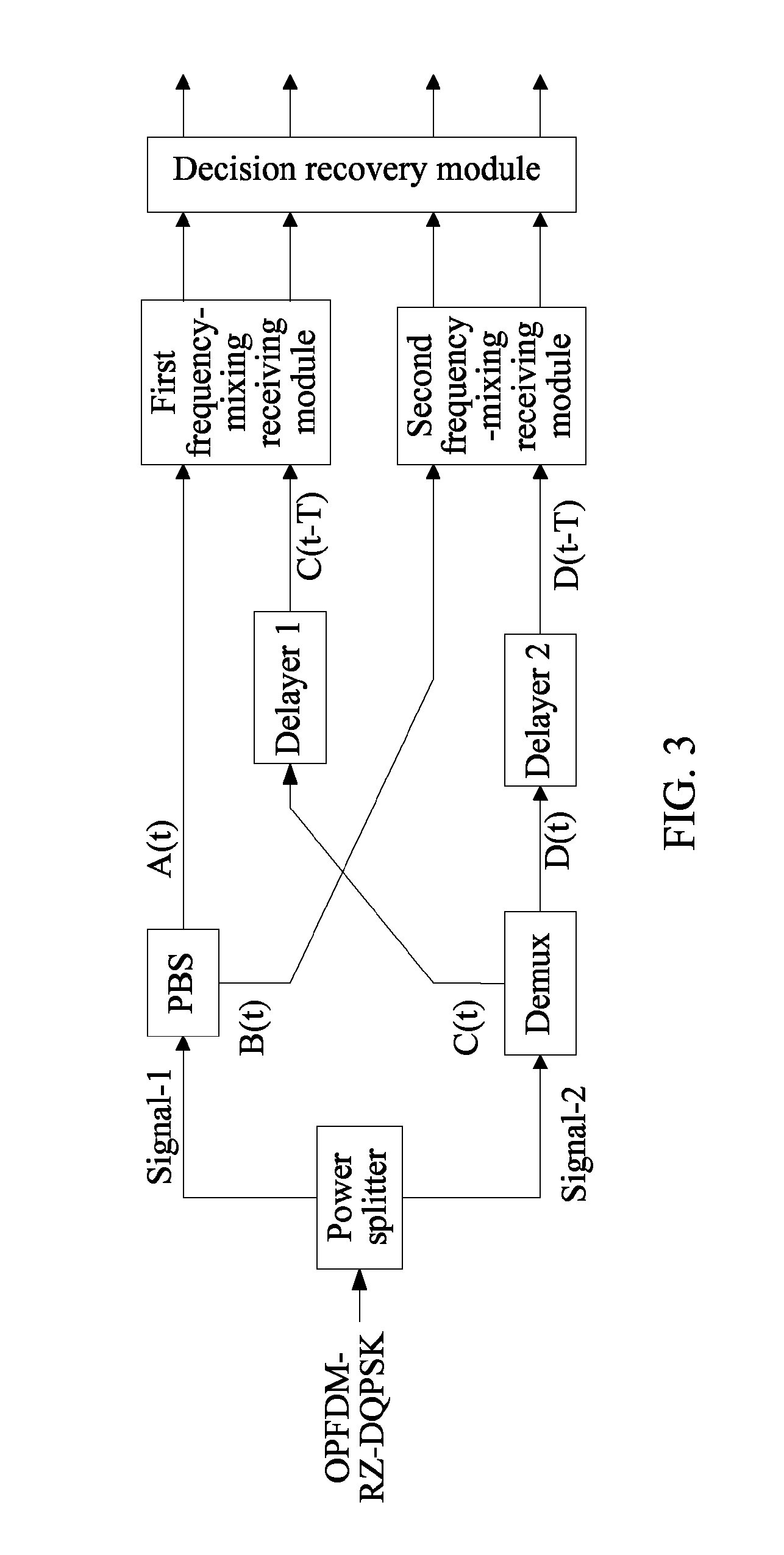
[0025]In the embodiments of the present invention, the PBS performs polarization splitting on the OPFDM-DQPSK signal to obtain two orthogonal polarized signals. The two polarized signals do not have any coherence, and frequencies of the two signals are respectively the same as frequencies of the two sub-carriers in the OPFDM-DQPSK signal. When delay frequency-mixing-coherence is performed on one of the two signals from the Demux and one of the two polarized signals, the problem that the Demux cannot completely eliminate crosstalk between adjacent sub-carriers in actual applications is effectively solved. The adopted decision recovery module includes low-pass filters capable of further eliminating the crosstalk between the adjacent sub-carriers. Through the present invention, the crosstalk between adjacent sub-carriers may be effectively eliminated, and the receiving performances of the device for receiving the OPFDM-DQPSK signal are enhanced, for example, a differential group delay tolerance and a CD dispersion tolerance of the receiving device are greatly improved.

Problems solved by technology

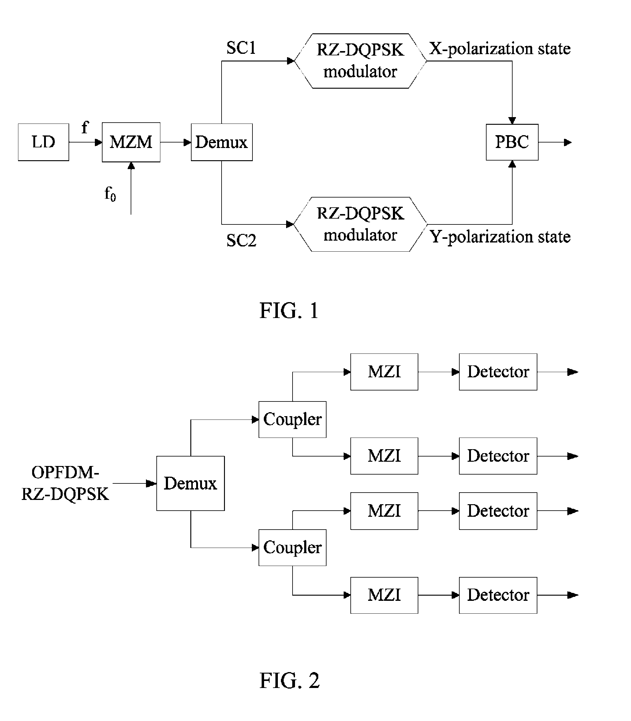
During the process of implementing the present invention, the inventor found that in the receiving method of the conventional art, the two sub-carriers are separated in the frequency domain by using the Demux, but it is difficult for the Demux to completely eliminate crosstalk caused by the interaction of the two sub-carriers in the frequency domain, resulting in error recovered data.

Method used


Image

  • Method and device for receiving OPFDM-DQPSK signal
  • Method and device for receiving OPFDM-DQPSK signal
  • Method and device for receiving OPFDM-DQPSK signal

Examples


Embodiment Construction

[0033]In order to make it easier for persons of ordinary skill in the art to understand and implement the present invention, embodiments of the present invention are described below with reference to the accompanying drawings. Here, the exemplary embodiments of the present invention and descriptions thereof are intended to illustrate the present invention, instead of limiting the present invention.

[0034]In the following embodiments, a process of receiving an OPFDM-RZ-DQPSK signal is set as an example for illustration. It should be understood that a process of receiving an OPFDM-NRZ-DQPSK is similar.

[0035]FIG. 3 is a schematic structural view of a device for receiving an OPFDM-RZ-DQPSK signal according to an embodiment of the present invention. Referring to FIG. 3, the device includes a power splitter, a PBS, a Demux, a delayer 1, a delayer 2, a first frequency-mixing receiving module, a second frequency-mixing receiving module, and a decision recovery module.

[0036]The power splitter...


PUM


Abstract

In the field of communication and transmission, a method and a device for receiving an OPFDM-DQPSK signal are provided. The device includes a power splitter, adapted to split the OPFDM-DQPSK signal into two beams of signals; a polarization beam splitter (PBS), adapted to splitting one of the two beams of signals into a first signal and a second signal; a demultiplexer (Demux), adapted to demultiplex the other beam of signal to obtain a third signal and a fourth signal; two delayers, adapted to delay the third signal and the fourth signal respectively; a first frequency-mixing receiving module, adapted to perform frequency-mixing receiving on the first signal and the delayed third signal; a second frequency-mixing receiving module, adapted to perform frequency-mixing receiving on the second signal and the delayed fourth signal; and a decision recovery module, adapted to recover four logical sequences by performing decision on the four electrical signals.

Description

CROSS-REFERENCE TO RELATED APPLICATION[0001]This application claims priority to Chinese Patent Application No. 200810242163.5 filed Dec. 30, 2008, the content of which is hereby incorporated by reference in its entirety.FIELD OF THE TECHNOLOGY[0002]The present invention relates to the field of communications, and more particularly to a method and a device for receiving an orthogonal polarized frequency division multiplexed-differential quadrature phase shift keying (OPFDM-DQPSK) signal.BACKGROUND OF THE INVENTION[0003]In high-speed optical communication, DQPSK is considered as the most potential modulation format. In the industry, researches on the DQPSK modulation format are competitively performed, and an orthogonal polarized frequency division multiplexed-return to zero-differential quadrature phase shift keying (OPFDM-RZ-DQPSK) modulation format is proposed, which has great tolerance on polarization mode dispersion (PMD), chromatic dispersion (CD), and non-linearity.[0004]FIG. 1...

Claims


Application Information

Patent Timeline
Patent Type & Authority Patents(United States)
IPC IPC(8): H04L27/22H03D3/22H04B10/67
CPCH04B10/677
Inventor LI, LIANGCHUANZHAO, CHANWEI, LUN
Owner HUAWEI TECH CO LTD
Learn More