Optical network terminal agent

a technology of optical network terminal and agent, applied in the field of optical network terminal agent, can solve the problems of onts that may malfunction, and onts that may interfere with upstream communication in a number of ways

Active Publication Date: 2011-11-22
VERIZON PATENT & LICENSING INC
View PDF17 Cites 15 Cited by
  • Summary
  • Abstract
  • Description
  • Claims
  • Application Information

AI Technical Summary

Problems solved by technology

Existing systems have drawbacks wherein ONTs may malfunction and interfere with the timeslots of ONTs on upstream communication.
The rogue ONT may interfere with upstream communications in a number of ways.
For example, a rogue ONT may have timing or synchronization problems wherein an upstream communication is transmitted in the assigned time of another ONT in the TDM scheme.
Further, an ONT may overload the OLT with too much optical power.
The result of the overload, may include, for example, either an inability for the OLT to receive the desired signal or an interference with other ONTs.
This is especially an issue where the rogue ONT is optically close to the OLT, while the ONT with the desired signal is at the edge of the supported distance or optical budget.
Additionally, the rogue ONT may confuse the PON to such an extent that a majority of the processing power of the PON is consumed and regular communication with the ONTs is interrupted.

Method used


Image

  • Optical network terminal agent
  • Optical network terminal agent
  • Optical network terminal agent

Examples


Embodiment Construction

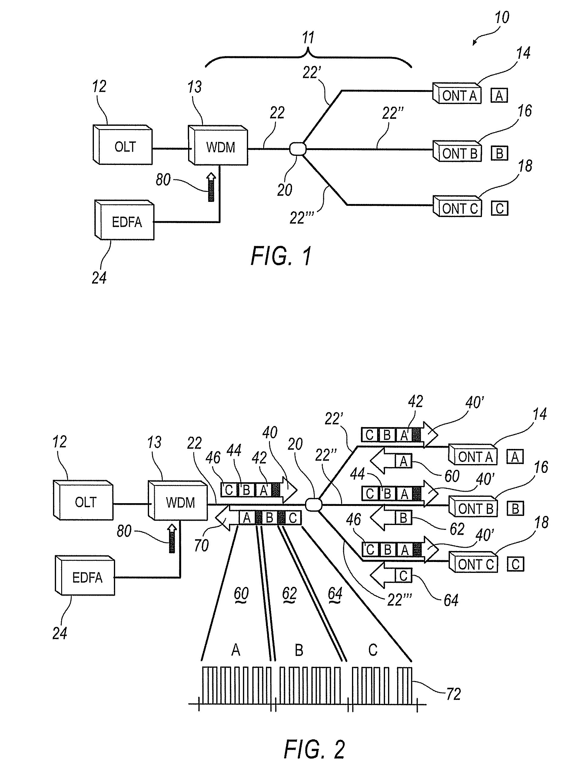
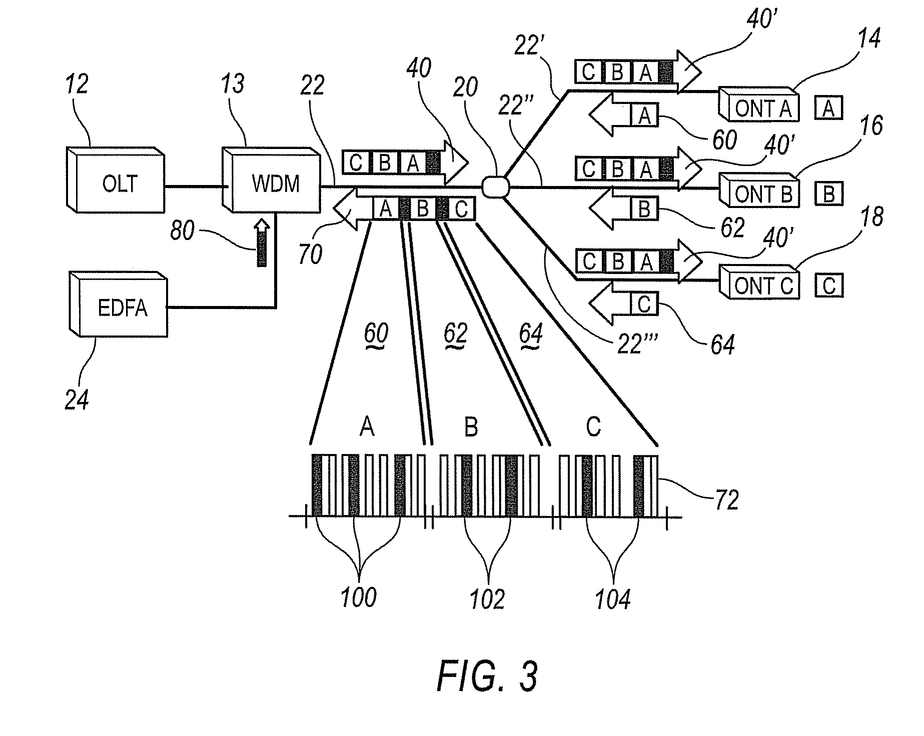
[0019]Referring now to the drawings, illustrative embodiments are shown in detail. Although the drawings represent the embodiments, the drawings are not necessarily to scale and certain features may be exaggerated to better illustrate and explain an innovative aspect of an embodiment. Further, the embodiments described herein are not intended to be exhaustive or otherwise limit or restrict the invention to the precise form and configuration shown in the drawings and disclosed in the following detailed description.

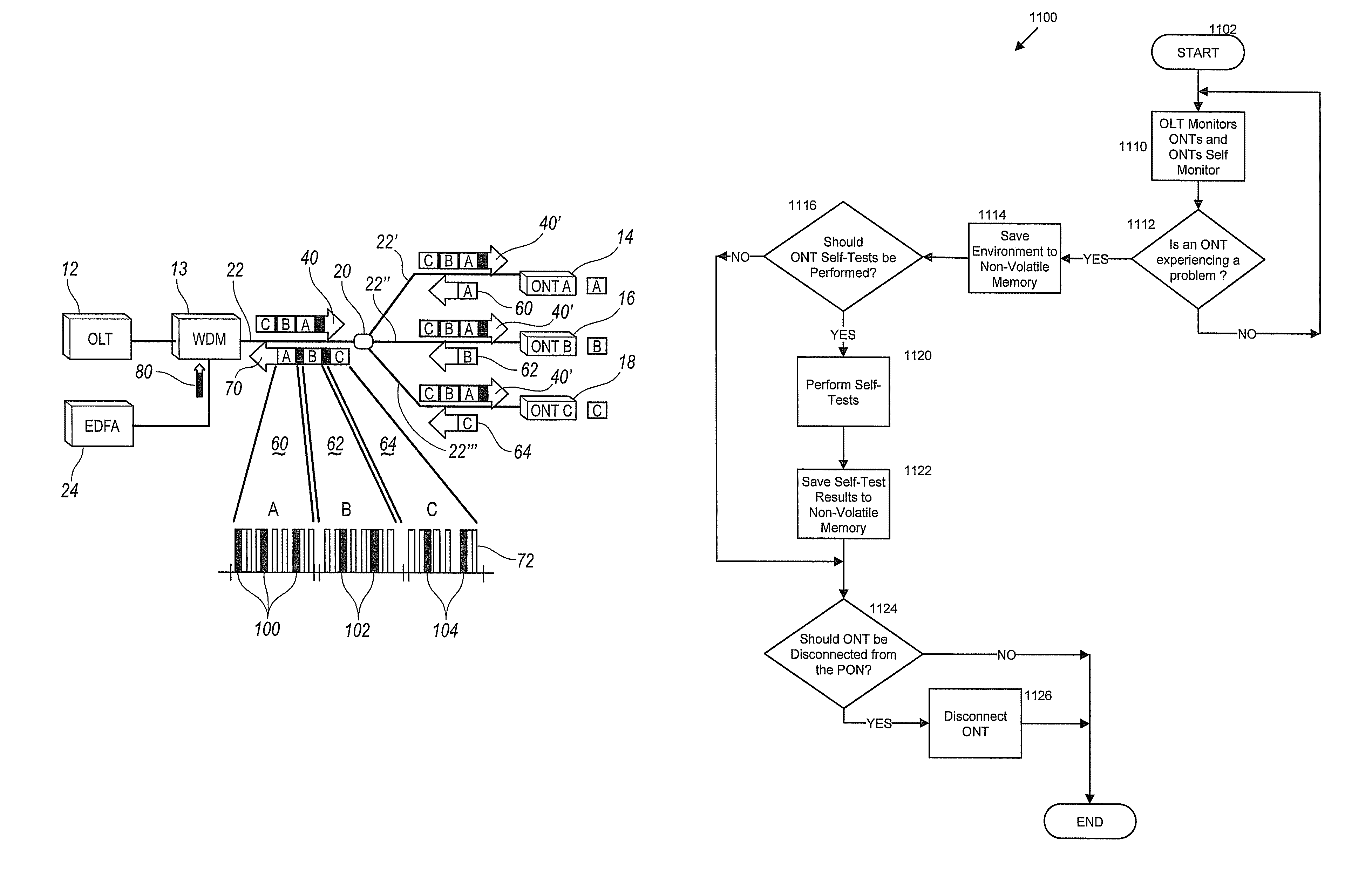
[0020]The systems and methods described herein use an agent(s) to determine whether or not a network component is malfunctioning or otherwise causing performance degradation of a communication system. The agent(s), e.g., a hardware detector, a software process, monitor internal features and / or external features of network components to detect malfunctions and to determine whether a rogue network component exists. Based on a determination that a rogue network component exist...


PUM


Abstract

A method is provided including the steps of monitoring at least one performance metric of at least one network component in an optical network system, determining whether the at least one network component is a rogue network component using the at least one performance metric, saving environment data to a non-volatile storage medium, and modifying the operation of the rogue network component to reduce interference of the rogue network component with the optical network system. In another embodiment, a method includes detecting a condition of a network component in an optical network system, and writing environment data of the network component to a non-volatile storage medium.

Description

BACKGROUND INFORMATION[0001]Optical networking transport systems typically use an optical line terminal (OLT) that provides a high bandwidth passive optical network (PON). The PON is split, using an optical splitter, to multiple optical network termination (ONT) points. The use of, for example, thirty two (32) ONTs allows multiple users to share the same high bandwidth OLT. However, the number of ONTs may be expanded to up to one hundred and twenty eight (128) in some implementations[0002]In use, the OLT and ONTs communicate with the PON using a time division multiplexing (TDM) scheme to allow for each ONT to communicate in an orderly fashion. The use of the optical splitter allows each ONT to share the same OLT and share the costs for the PON system. The TDM scheme is a method for transmitting multiple channels over the single PON line. Each ONT is assigned a periodic timeslot to receive and transmit to the OLT. Thus, there are two slots available to an ONT that include a downstrea...

Claims


Application Information

Patent Timeline
Patent Type & Authority Patents(United States)
IPC IPC(8): H04B10/08
CPCH04B10/0793H04J3/0682H04J3/1694H04J14/0282H04J14/0247H04J14/0252H04J14/0226
Inventor O'BYRNE, VINCENT A.WHITTON, BRIAN
Owner VERIZON PATENT & LICENSING INC
Why Eureka
Try Eureka