
Blood processing apparatus with controlled cell capture chamber trigger

a technology of blood processing apparatus and trigger, which is applied in the direction of centrifuges, separation processes, filtration separation, etc., can solve the problems of reducing the “platelet viability” of the platelet, introducing its own set of problems, and conventional porous filter may be inefficient, so as to improve the donation process, improve the collection procedure, and improve the effect of white blood cell collection

Active Publication Date: 2011-11-29
TERUMO BCT
View PDF47 Cites 6 Cited by
  • Summary
  • Abstract
  • Description
  • Claims
  • Application Information

AI Technical Summary

Benefits of technology

This approach enables efficient and high-quality collection of white blood cells, reducing donation time and improving platelet viability by accurately detecting and separating white blood cells, even under unstable flow conditions.

Problems solved by technology

However, use of the porous filter introduces its own set of problems.
Conventional porous filters may be inefficient because they may permanently remove or trap approximately 5-20% of the platelets.
These conventional filters may also reduce “platelet viability”, meaning that once the platelets pass through a filter, a percentage of the platelets cease to function properly and may be partially or fully activated.
In addition, porous filters may cause the release of bradykinin, an inflammation mediator and vasodialator, which may lead to hypotensive episodes in a patient.
Porous filters are also expensive and often require additional time-consuming manual labor to perform a filtration process.
Although porous filters are effective in removing a substantial number of white blood cells, activated platelets may clog the filter.
Therefore, the use of at least some porous filters is not feasible in on-line processes.
Thus, some elutriation processes only permit separation in particle batches and require an additional fluid medium to transport particles.

Method used


Image

  • Blood processing apparatus with controlled cell capture chamber trigger
  • Blood processing apparatus with controlled cell capture chamber trigger
  • Blood processing apparatus with controlled cell capture chamber trigger

Examples


Embodiment Construction

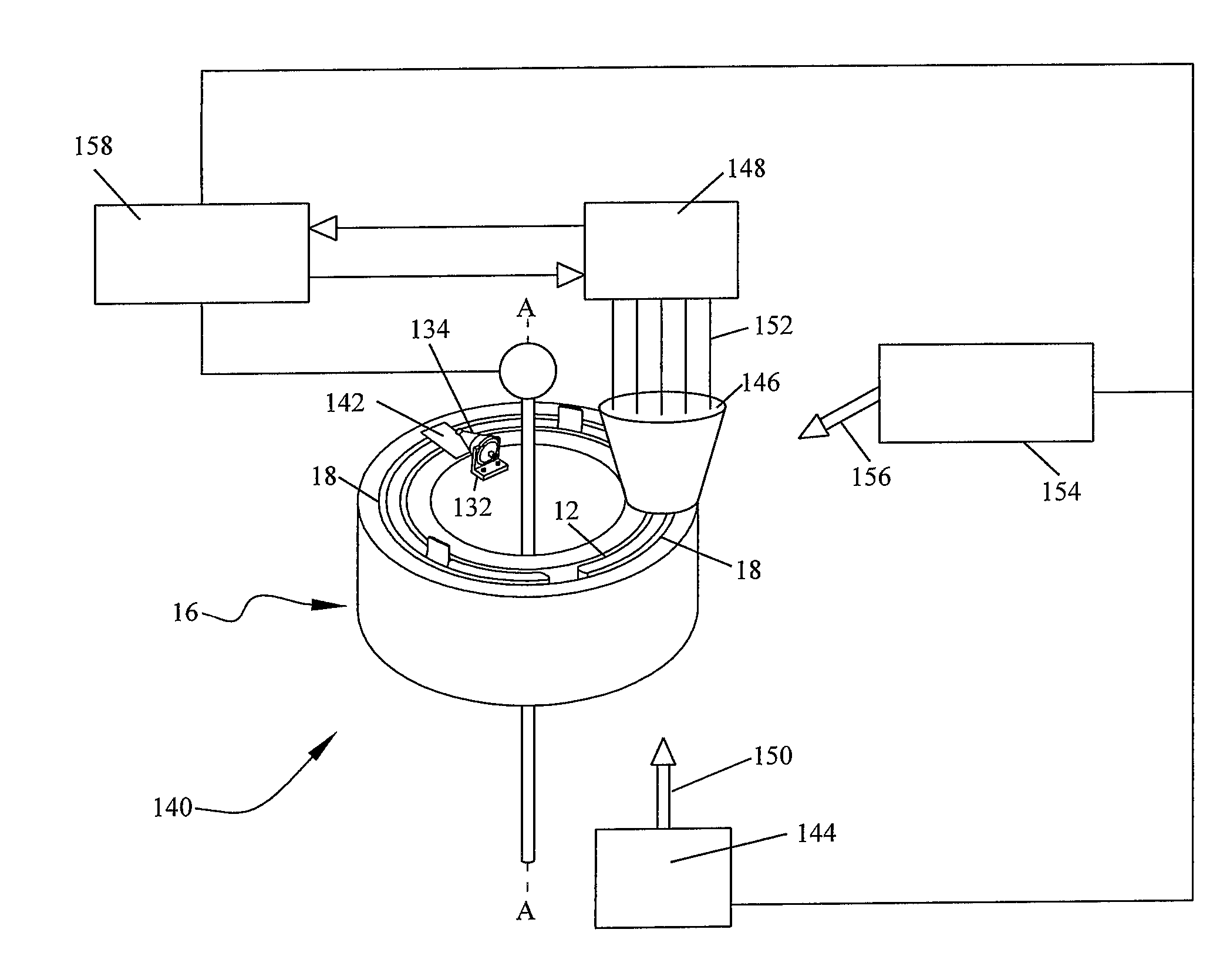
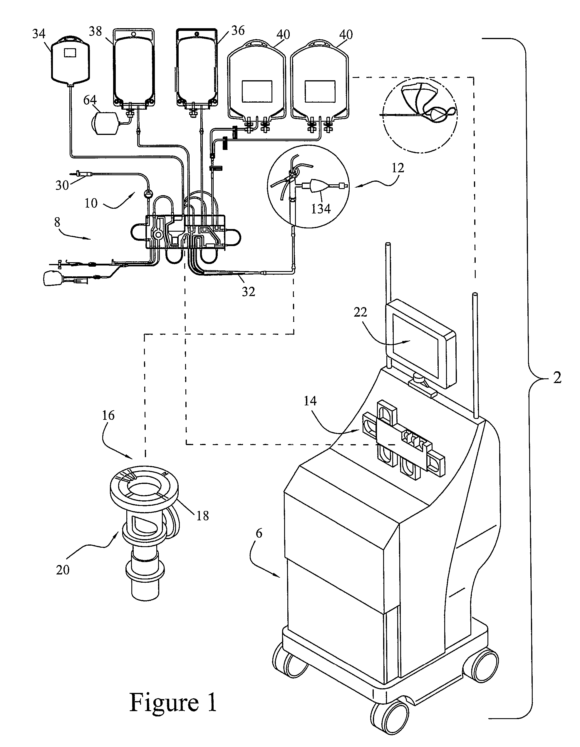
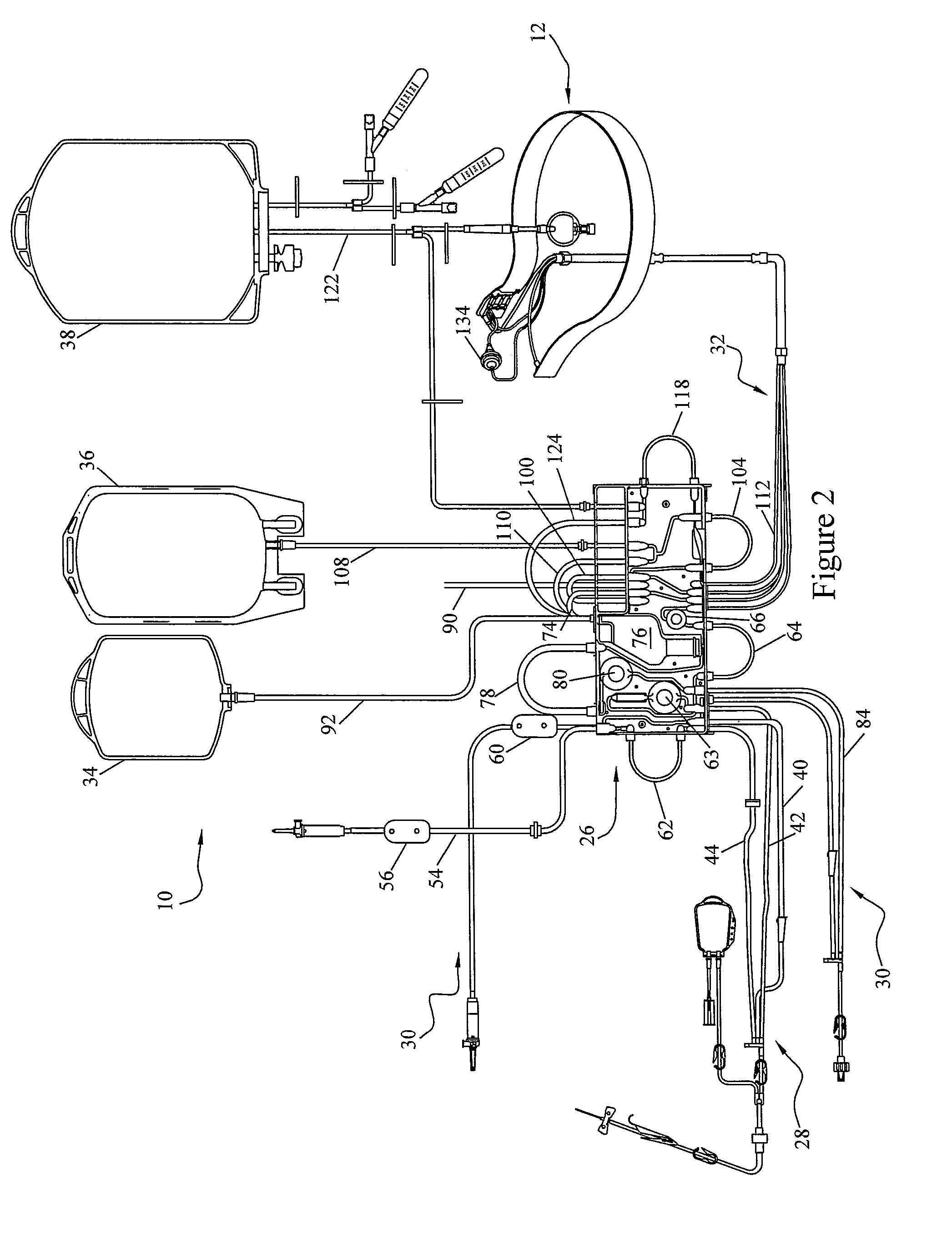
[0030]To describe the present invention, reference will now be made to the accompanying drawings. The present invention comprises a blood processing apparatus having a camera control system, as disclosed in U.S. patent application Ser. No. 11 / 163,969, application Ser. No. 10 / 884,877 and application Ser. No. 10 / 905,353. It may also be practiced with a TRIMA® blood component centrifuge manufactured by Gambro BCT, Inc. of Colorado or, alternatively, with a COBE® SPECTRA™ single-stage blood component centrifuge also manufactured by Gambro BCT, Inc. Both the TRIMA® and the SPECTRA™ centrifuges incorporate a one-omega / two-omega sealless tubing connection as disclosed in U.S. Pat. No. 4,425,112 to Ito, the entire disclosure of which is incorporated herein by reference. The SPECTRA™ centrifuge also uses a single-stage blood component separation channel substantially as disclosed in U.S. Pat. No. 4,094,461 to Kellogg et al. and U.S. Pat. No. 4,647,279 to Mulzet et al., the entire disclosures...


PUM

PropertyMeasurementUnit
thicknessaaaaaaaaaa
optical characteristicsaaaaaaaaaa
length of timeaaaaaaaaaa

Abstract

A blood cell collection system having means for detecting when a cell separation chamber has filled with white blood cells, and flushing the cells out of the cell separation chamber into a collect bag. A red-green sensor senses the optical characteristics of fluid leaving the cell separation chamber. A baseline value is calculated. The device calculates a ratio of the intensities of red light and green light and a peak-to-peak ratio of intensities. If either ratio exceeds thresholds computed from the baseline, the device flushes the cells into the collect bag. A camera detects white cells passing into the cell separation chamber and the device calculates the number of cells being collected. If the calculated number of collected cells exceeds a certain limit, the cell separation chamber is flushed. If the device is unable to establish a baseline, the donation can proceed, relying solely on the calculated number of collected cells.

Description

[0001]This application claims priority of U.S. Provisional application Ser. No. 61 / 017,045 filed Dec. 27, 2007. This application is related to U.S. patent application Ser. No. 11 / 163,969, filed Nov. 4, 2005, published on May 10, 2007 as Pub. No. 2007 / 0102374A1, and now abandoned. Further related patents include U.S. Pat. No. 5,722,926, issued Mar. 3, 1998; U.S. Pat. No. 5,951,877, issued Sep. 14, 1999; U.S. Pat. No. 6,053,856, issued Apr. 25, 2000; U.S. Pat. No. 6,334,842, issued Jan. 1, 2002; U.S. Pat. No. 7,422,693 B2, issued Sep. 9, 2008; and U.S. Pat. No. 7,327,443 B2, issued Feb. 5, 2008. The entire disclosures of the provisional patent application, the patent publication and all of the U.S. patents are incorporated herein by reference.FIELD OF THE INVENTION[0002]The present invention relates to an apparatus and method for separating particles or components of a fluid. The invention has particular advantages in connection with separating blood components, such as white blood ce...

Claims


Application Information

Patent Timeline
Patent Type & Authority Patents(United States)
IPC IPC(8): B01D21/32
CPCA61M1/3693A61M2205/123A61M2205/3313A61M1/3696A61M1/36224A61M1/362266A61M1/36222A61M1/362262A61M1/36226A61M1/36225
Inventor SWEAT, WILLIAMKOLENBRANDER, JEREMYLINDNER, JOHN R.HINZ, JENNIFER
Owner TERUMO BCT
Learn More