
Power supply circuits

a power supply circuit and circuit technology, applied in the direction of dc source parallel operation, pulse technique, sustainable buildings, etc., can solve problems such as faults interfering with the correct operation of photovoltaic power conditioning, and achieve the effect of facilitating monitoring conditions

Active Publication Date: 2011-11-29
TESLA INC
View PDF39 Cites 179 Cited by
  • Summary
  • Abstract
  • Description
  • Claims
  • Application Information

AI Technical Summary

Benefits of technology

Directly coupling the electronic controller to the power supply line facilitates monitoring of conditions on the line rather than needing to infer these from a measurement made at some earlier point in the supply of power from the PV device to the mains. Such indirect measurements risk a fault interfering with correct operation of the photovoltaic power conditioning and, in particular, of the aforementioned islanding.

Problems solved by technology

Such indirect measurements risk a fault interfering with correct operation of the photovoltaic power conditioning and, in particular, of the aforementioned islanding.

Method used


Image

  • Power supply circuits
  • Power supply circuits
  • Power supply circuits

Examples


Embodiment Construction

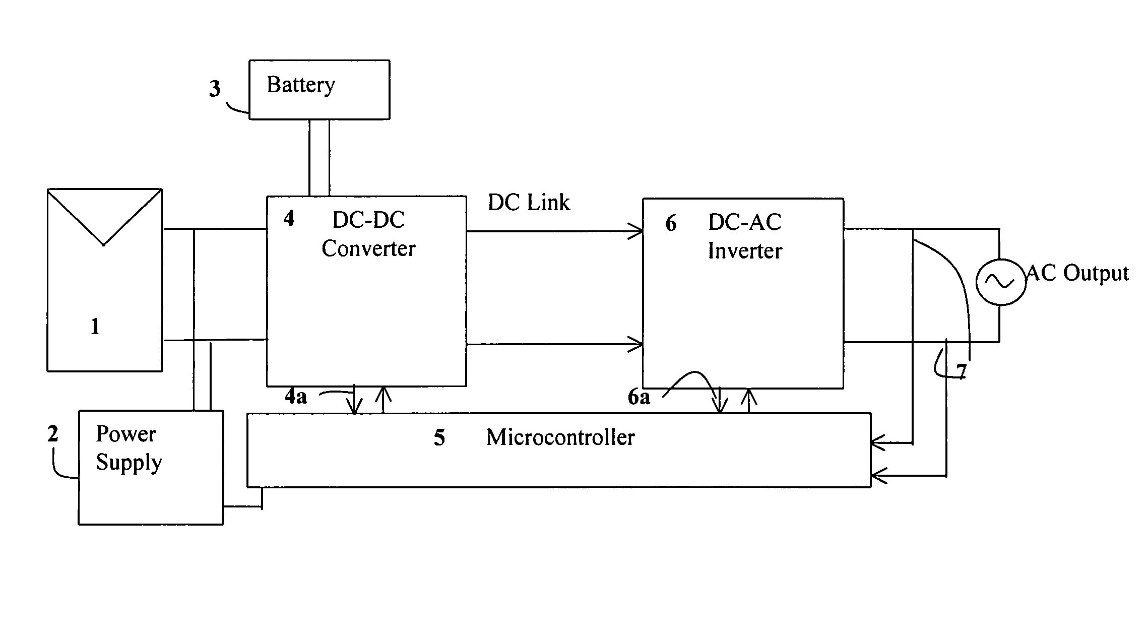
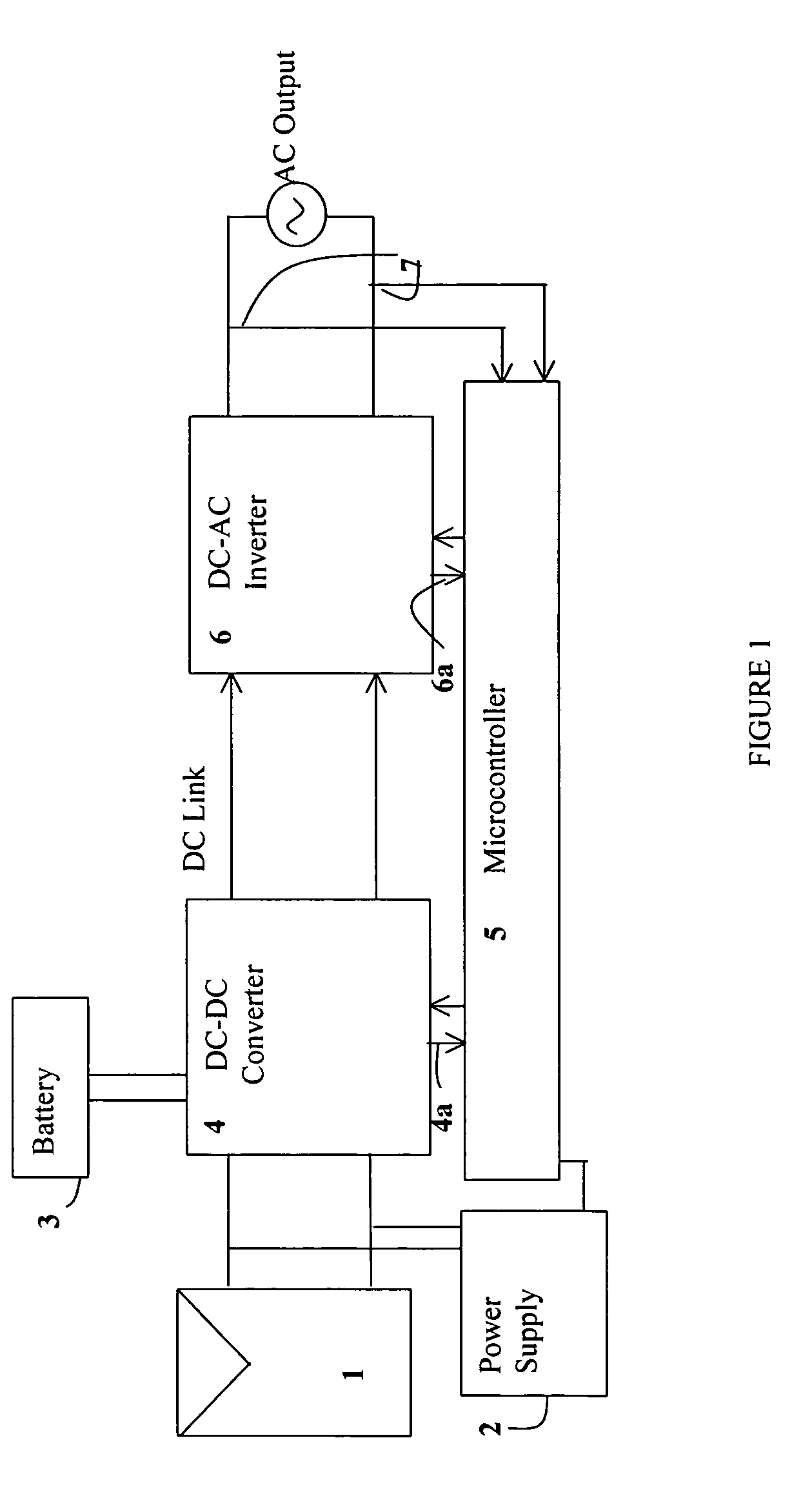
Referring to FIG. 1 this shows an overall block diagram of a grid-connected photovoltaic inverter and battery controller. The photovoltaic module is shown as object 1 in FIG. 1, which is connected to the DC to DC converter. The 5V rail for the microcontroller is generated using the power supply (2), which takes the input directly from the photovoltaic module. The microcontroller is connected to the DC-DC converter 4, DC-AC converter 6 and the output 7. Depending on the condition that the controller senses at 7 point it varies the control of the power conditioning blocks via control connections 4a and 6a accordingly. The illustrated configuration is also designed to charge a battery 3, shown connected from the DC-DC converter block.

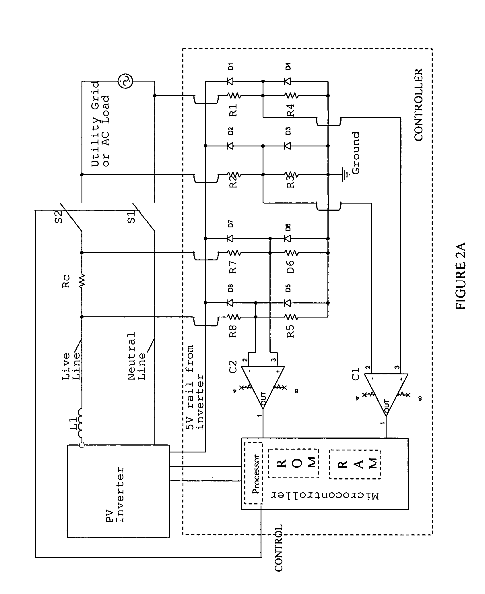
FIG. 2a shows an example of microcontroller to grid interface configuration. The figure shows how the PV inverter is connected to the mains and shows the configuration of the feedback to inverter via the microcontroller. The microcontroller is used to moni...


PUM


Abstract

This invention is generally concerned with power supply circuits, and more particularly, with circuits to supply power to a mains supply, such as domestic grid mains, from a photovoltaic device. A photovoltaic power conditioning circuit for providing power from a photovoltaic device to an alternating current mains power supply line, the circuit comprising: a DC input to receive DC power from said photovoltaic device; an AC output configured for direct connection to said AC mains power supply line; a DC-to-AC converter coupled to said DC input and to said AC output to convert DC power from said photovoltaic device to AC power for output onto said power supply line; and an electronic controller directly coupled to said power supply line to measure a voltage of said power supply line and a current in said supply line and to control said DC-to-AC converter responsive to said measuring.

Description

TECHNICAL FIELDThis invention is generally concerned with power supply circuits, and more particularly, with circuits to supply power to a mains supply, such as domestic grid mains, from a photovoltaic device.BACKGROUNDIt is known to provide an alternating current mains supply at either 110 volts or 230 / 240 volts from a photovoltaic device using an inverter circuit. One standard photovoltaic (PV) panel provides approximately 20 volts DC at around 4.5 amps maximum and this voltage must be stepped up and converted to alternating current to provide a mains output. This is generally done using an inverter constructed from discrete electronic components to convert the low DC input voltage to a high AC output voltage. Alternatively, there may be an initial step to step up the DC voltage before converting it to an AC voltage. An implementation of such a basic arrangement using the Hitachi ECN 3067 integrated circuit and, optionally, the ST Microelectronics L298 integrated circuit is descri...

Claims


Application Information

Patent Timeline
Patent Type & Authority Patents(United States)
IPC IPC(8): H02J1/12
CPCH02M7/4807H02J3/383H01L27/1203H03K17/6871Y02B10/14Y02E10/563Y10T307/625Y10T307/527Y10T307/511H02J2300/24H02J3/381Y02B10/10Y02E10/56H02J2300/26H02J3/388
Inventor MUMTAZ, ASIMCHISENGA, LESLEYAMARATUNGA, GEHAN ANIL JOSEPH
Owner TESLA INC
Learn More