
Method for locating phase to ground faults in DC distribution systems

a technology of dc distribution system and ground fault, applied in the direction of short-circuit testing, emergency protective arrangements for limiting excess voltage/current, instruments, etc., can solve problems such as disturbances in noise patterns

Active Publication Date: 2011-11-29
FLORIDA STATE UNIV RES FOUND INC
View PDF3 Cites 20 Cited by
  • Summary
  • Abstract
  • Description
  • Claims
  • Application Information

AI Technical Summary

Problems solved by technology

Faults occurring in such a system cause disturbances in the noise patterns detected within the power supply to the system.

Method used


Image

  • Method for locating phase to ground faults in DC distribution systems
  • Method for locating phase to ground faults in DC distribution systems
  • Method for locating phase to ground faults in DC distribution systems

Examples


Embodiment Construction

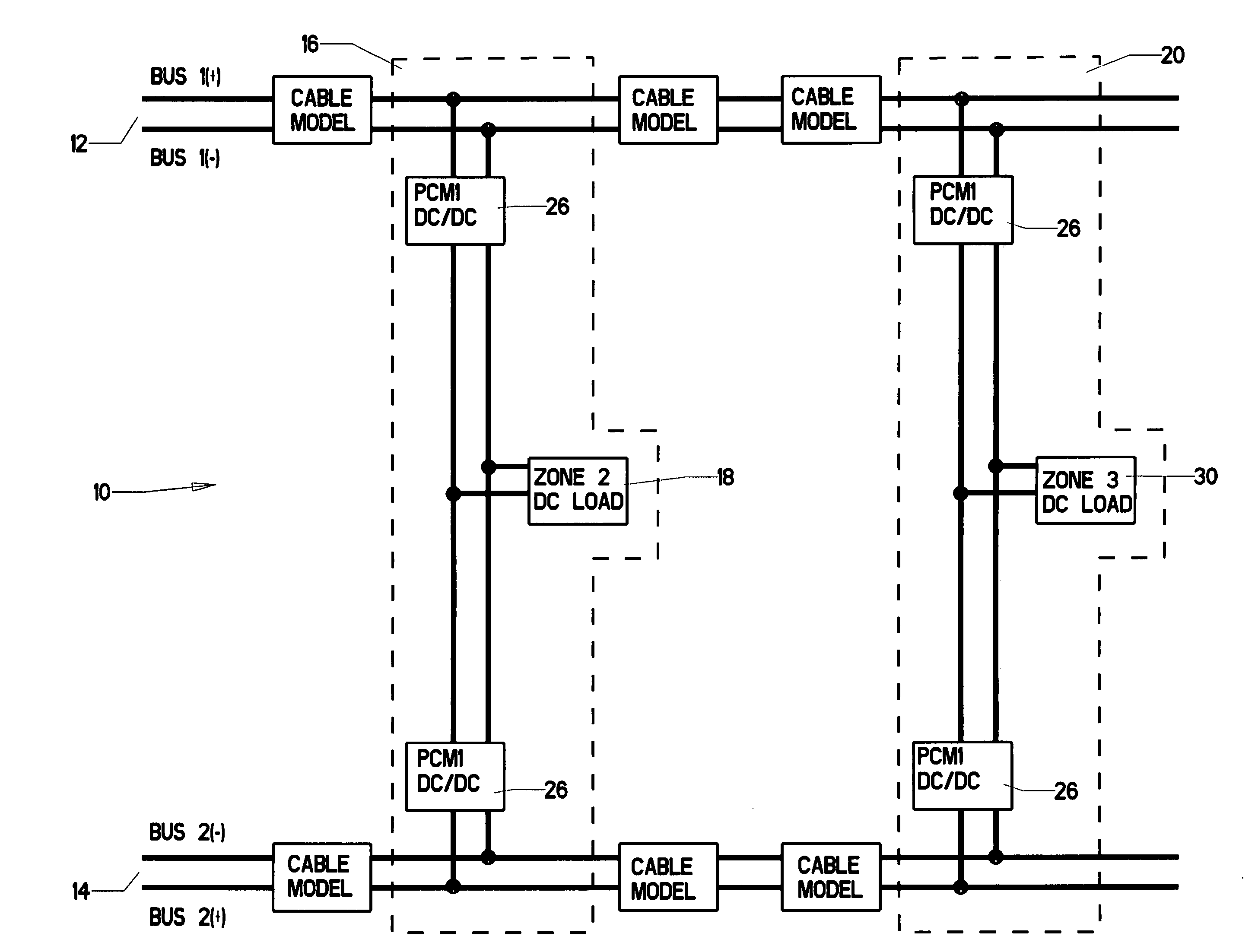
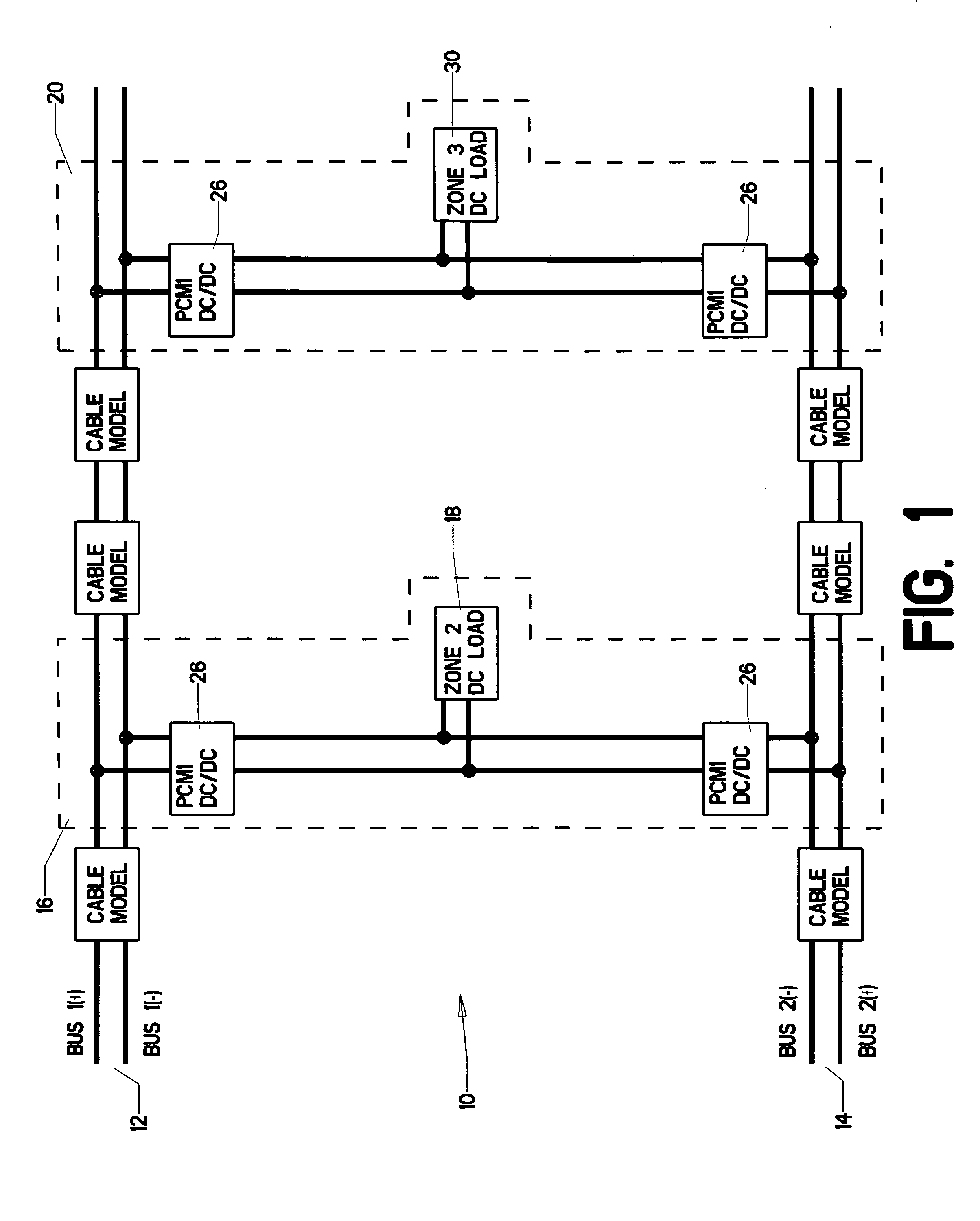
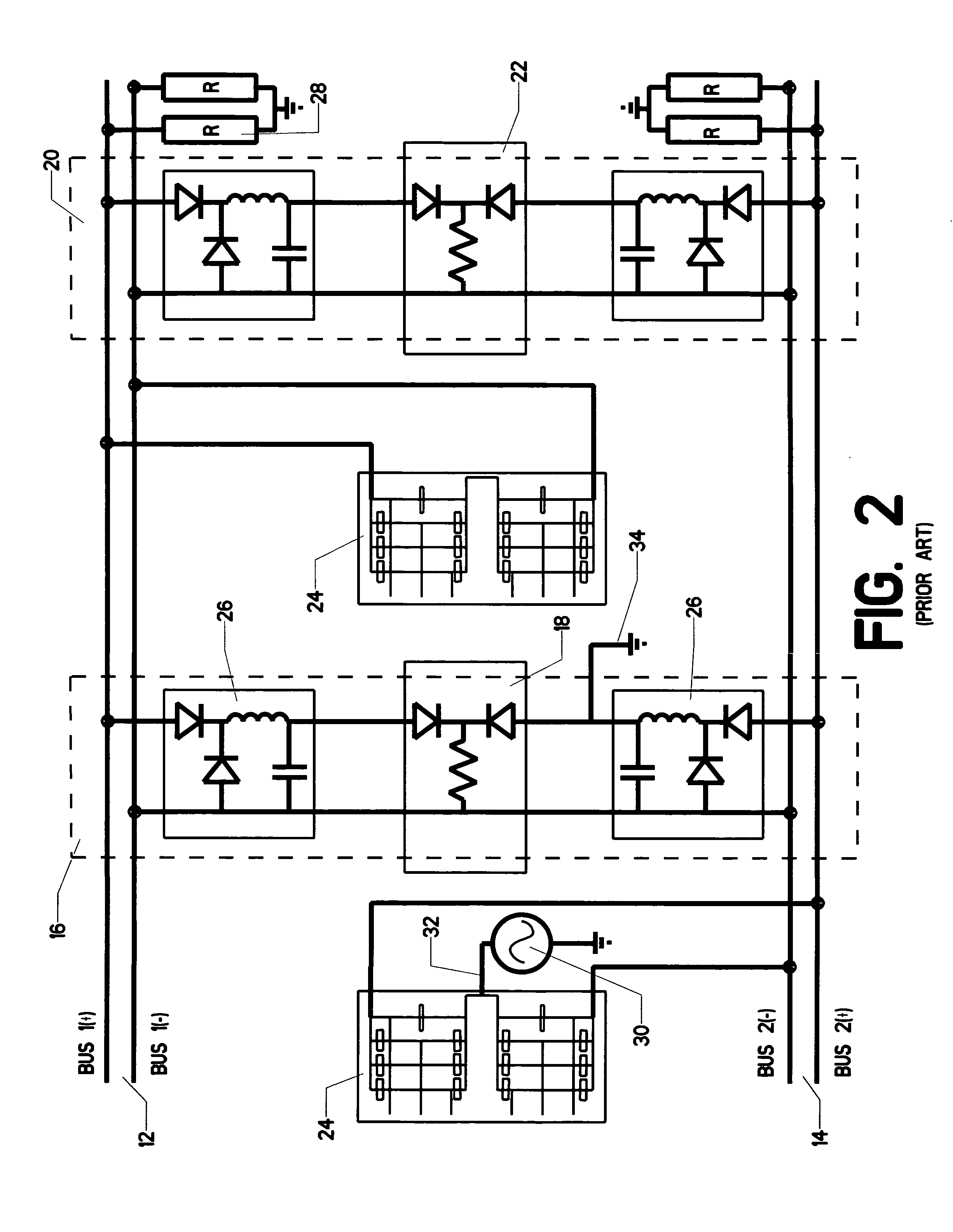
[0027]The present invention is a method for locating phase to ground faults in ungrounded or high-resistance grounded DC power distribution systems utilizing the switching noise contained in a suitable signal. Such a signal might be, for example, a voltage signal measured between the mid point of a voltage divider circuit (preferably a capacitive circuit) and ground to extract information about the fault locations. In any real DC distribution system which contains power electronic (PE) switching converters for voltage and power flow control, such a signal will always contain a certain amount of high frequency noise. This is caused by repetitive switching transients introduced by the PE converters interacting with parasitic elements (i.e. cable insulation capacitances) in the system. In case of a phase-to-ground fault, this voltage signal contains characteristic information in the high frequency range above the switching frequencies of the PE converters which allows for localization ...


PUM


Abstract

A method for locating phase to ground faults in DC distribution systems. The method includes utilizing wavelet analysis using Multi-Resolution Analysis (MRA) as a signal processing tool for recognition of characteristic features in the voltage signal. The voltage signal contains characteristic information in the high frequency range above the switching frequencies of the PE converters which allows for localization of the fault.

Description

CROSS-REFERENCES TO RELATED APPLICATIONS[0001]This is a non-provisional application claiming the benefit—pursuant to 37 C.F.R. §1.53(c)—of an earlier-filed provisional application. The provisional application was filed on Sep. 28, 2007 and was assigned application Ser. No. 60 / 995,952.BACKGROUND OF THE INVENTION[0002]1. Field of the Invention[0003]This invention relates to the field of electrical direct current distribution systems. More specifically, this invention comprises a method for locating phase to ground faults in DC distribution systems.[0004]2. Description of the Related Art[0005]Ungrounded or high-resistance grounded power systems have many advantages, including continuous operation after a single line to ground fault. While theoretically such an ungrounded DC system can be operated with one phase grounded through a fault, a secondary phase to ground fault on the other phase may occur causing a disruptive fault between the two phases. To reduce the probability of a second...

Claims


Application Information

Patent Timeline
Patent Type & Authority Patents(United States)
IPC IPC(8): G01R31/14G01R31/08H02H9/08
CPCG01R31/025G01R31/088H02H7/268G01R31/086G01R31/52
Inventor PAN, YANSILVEIRA, PAULOSTEURER, MICHAELBALDWIN, THOMASRIBEIRO, PAULO
Owner FLORIDA STATE UNIV RES FOUND INC
Learn More