
Surface acoustic wave filter, antenna duplexer and method for manufacturing them

a technology of surface acoustic wave and filter, which is applied in the direction of piezoelectric/electrostrictive devices, device material selection, piezoelectric/electrostrictive devices, etc., can solve the problems of spurious responses, poor temperature characteristics, and adverse effects of frequency bands on characteristics, and achieve superior characteristics and suppress spurious responses

Active Publication Date: 2011-12-06
SKYWORKS PANASONIC FILTER SOLUTIONS JAPAN
View PDF31 Cites 7 Cited by
  • Summary
  • Abstract
  • Description
  • Claims
  • Application Information

AI Technical Summary

Benefits of technology

[0018]The present invention is intended to solve the above problems of the conventional art, and to provide a surface acoustic wave filter and an antenna duplexer featuring superior characteristics with insignificant ripples while suppressing spurious responses of surface acoustic wave resonators. The present invention also provides a method of manufacturing such surface acoustic wave filter and antenna duplexer.
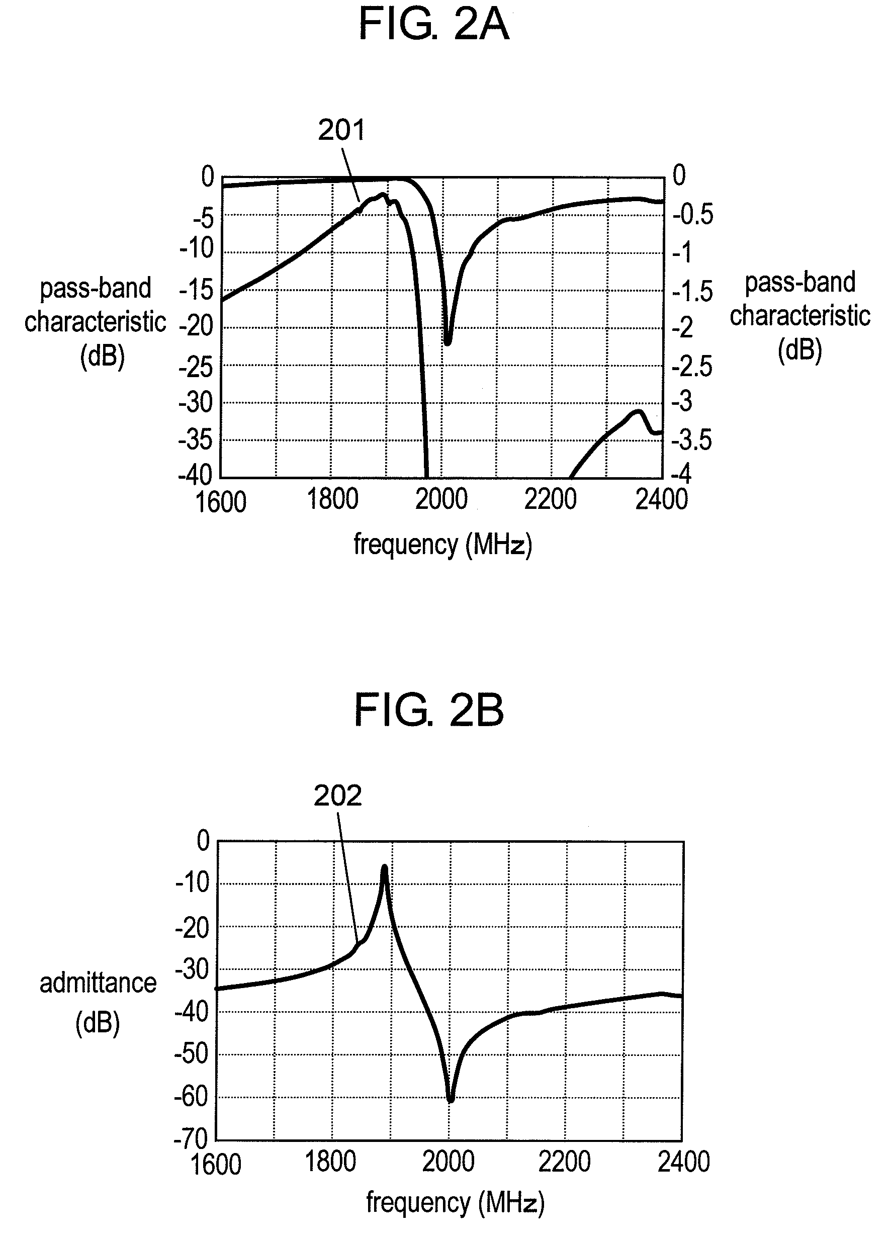
[0020]It becomes possible according to this structure to achieve the surface acoustic wave filter of superior characteristics with insignificant ripples while suppressing spurious responses.

Problems solved by technology

However, the surface acoustic wave filters using substrates of such kind have a drawback in general that they are poor in temperature characteristic.
There are cases that spurious responses occur due to resonances in the transverse mode when this type of substrate is used.
These types of conventional surface acoustic wave resonators thus have a drawback that ripples present within the frequency band adversely affect the characteristics when they are used for a ladder type filter or an antenna duplexer.[Patent Document 1] Japanese Patent Unexamined Publication, No. 2003-209458

Method used


Image

  • Surface acoustic wave filter, antenna duplexer and method for manufacturing them
  • Surface acoustic wave filter, antenna duplexer and method for manufacturing them
  • Surface acoustic wave filter, antenna duplexer and method for manufacturing them

Examples


Embodiment Construction

[0053]Referring now to the accompanying drawings, description is provided hereinafter of a surface acoustic wave filter and an antenna duplexer according to an exemplary embodiment of the present invention.

Exemplary Embodiment

[0054]First, a study was made on shapes of SiO2 films used as thin dielectric films, and evaluations performed on characteristics of surface acoustic wave resonators.

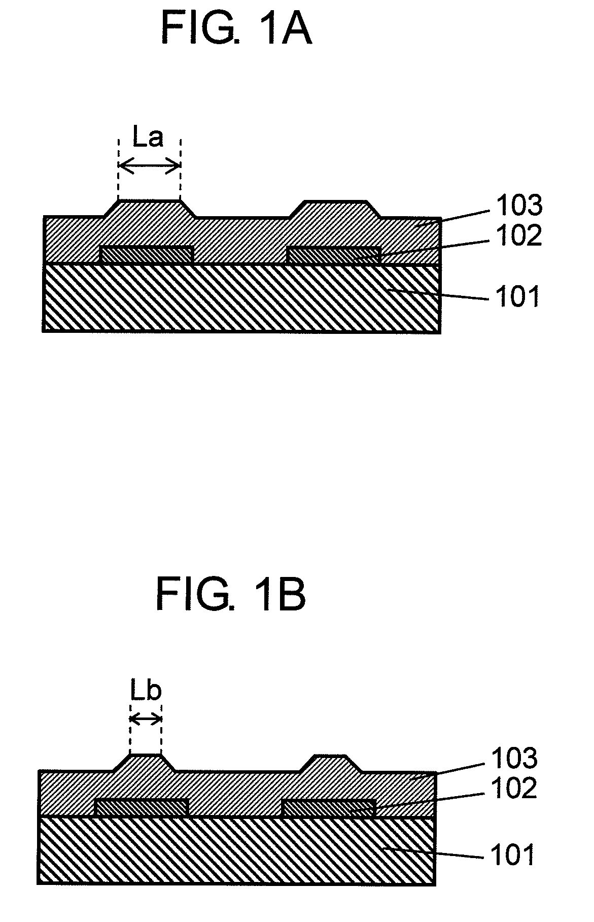
[0055]FIGS. 1A and 1B are schematic views of thin SiO2 films 103 formed on electrodes 102 on piezoelectric substrates 101 used as substrates. FIG. 1A shows the thin SiO2 film provided with raised portions above the electrodes, upper parts of the raised portions having large length La, and FIG. 1B shows the thin SiO2 film provided with raised portions above the electrodes, upper parts of the raised portions having small length Lb, wherein they have a relation of La>Lb. Any such shapes can be achieved by applying a bias voltage to the substrate, for instance, when SiO2 is being deposited. The shape o...


PUM


Abstract

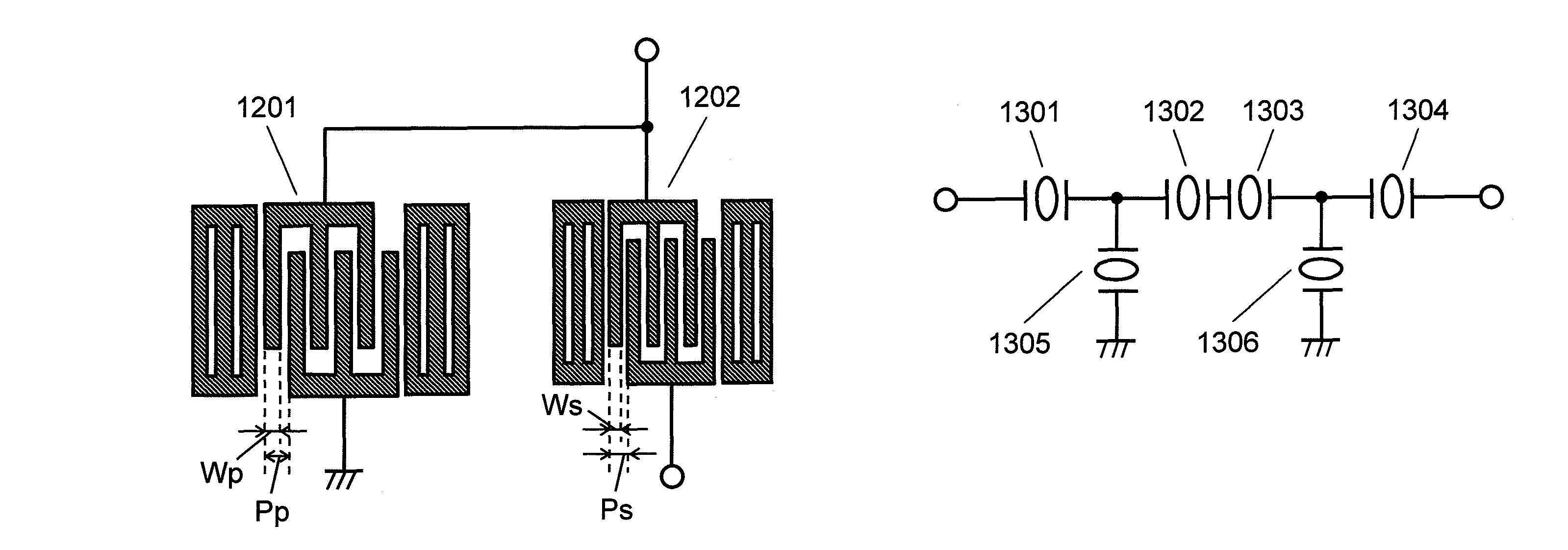
A surface acoustic wave filter comprised of a plurality of surface acoustic wave resonators having different resonance frequencies, the filter comprising a substrate made of lithium niobate, comb electrodes (1201 and 1202) formed on the substrate, and a thin dielectric film covering the comb electrodes (1201 and 1202), wherein the surface acoustic wave resonator having a lower resonance frequency is formed to have a metallization ratio larger than a metallization ratio of the surface acoustic wave resonator having a higher resonance frequency, thereby providing the surface acoustic wave filter and an antenna duplexer featuring superior characteristics with insignificant ripples while suppressing spurious responses of the surface acoustic wave resonators.

Description

TECHNICAL FIELD[0001]The present invention relates to surface acoustic wave filters, antenna duplexers, and a method for manufacturing them.BACKGROUND ART[0002]It has been the general practice to use piezoelectric substrates having large electromechanical coupling coefficients, such as lithium niobate (LiNbO3) substrates, in order to produce surface acoustic wave filters featuring wideband characteristics.[0003]However, the surface acoustic wave filters using substrates of such kind have a drawback in general that they are poor in temperature characteristic.[0004]To this end, patent document 1 discloses a structure contrived to improve the temperature characteristic.[0005]The structure disclosed in the patent document 1 comprises a LiNbO3 substrate and a thin layer of SiO2 film formed on the substrate, wherein the LiNbO3 substrate is a rotated Y-cut substrate having a cut angle set to a range of −10 to +30 degrees, and further wherein, when a film thickness of the thin layer and a w...

Claims


Application Information

Patent Timeline
Patent Type & Authority Patents(United States)
IPC IPC(8): H03H9/64H03H9/72H01L41/09H01L41/18H01L41/22H01L41/23H01L41/29H03H9/145H03H9/25
CPCH03H9/6496H03H9/725
Inventor NAKAMURA, HIROYUKIMATSUNAMI, KENTSURUNARI, TETSUYANAKANISHI, HIDEKAZU
Owner SKYWORKS PANASONIC FILTER SOLUTIONS JAPAN
Learn More