Unit circuit, electro-optical device, and electronic apparatus

a technology of electrooptical devices and electronic devices, applied in static indicating devices, instruments, transportation and packaging, etc., can solve the problems of difficult to obtain a sufficient period of time required for the compensation of variations in threshold voltage, non-uniform display state of each pixel, crosstalk produced by such capacitive coupling, etc., to achieve accurate compensation of threshold voltage variations and reliably write data voltage

Active Publication Date: 2011-12-06
ELEMENT CAPITAL COMMERCIAL CO PTE LTD
View PDF9 Cites 11 Cited by
  • Summary
  • Abstract
  • Description
  • Claims
  • Application Information

AI Technical Summary

Benefits of technology

[0009]Some exemplary embodiments of the invention avoid crosstalk. Some embodiments accurately compensate variations in threshold voltage in a drive transistor and reliably writes a data voltage.
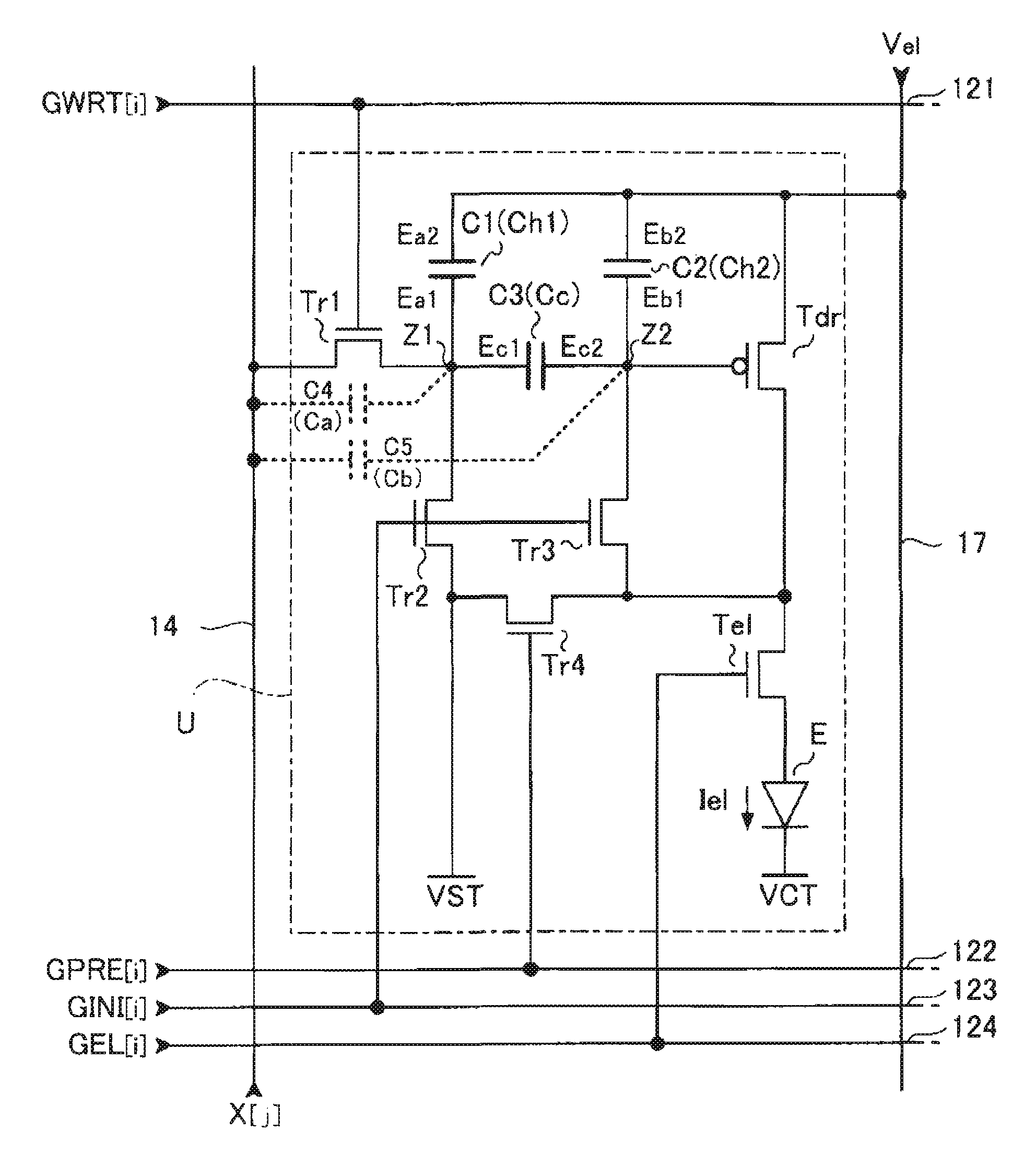
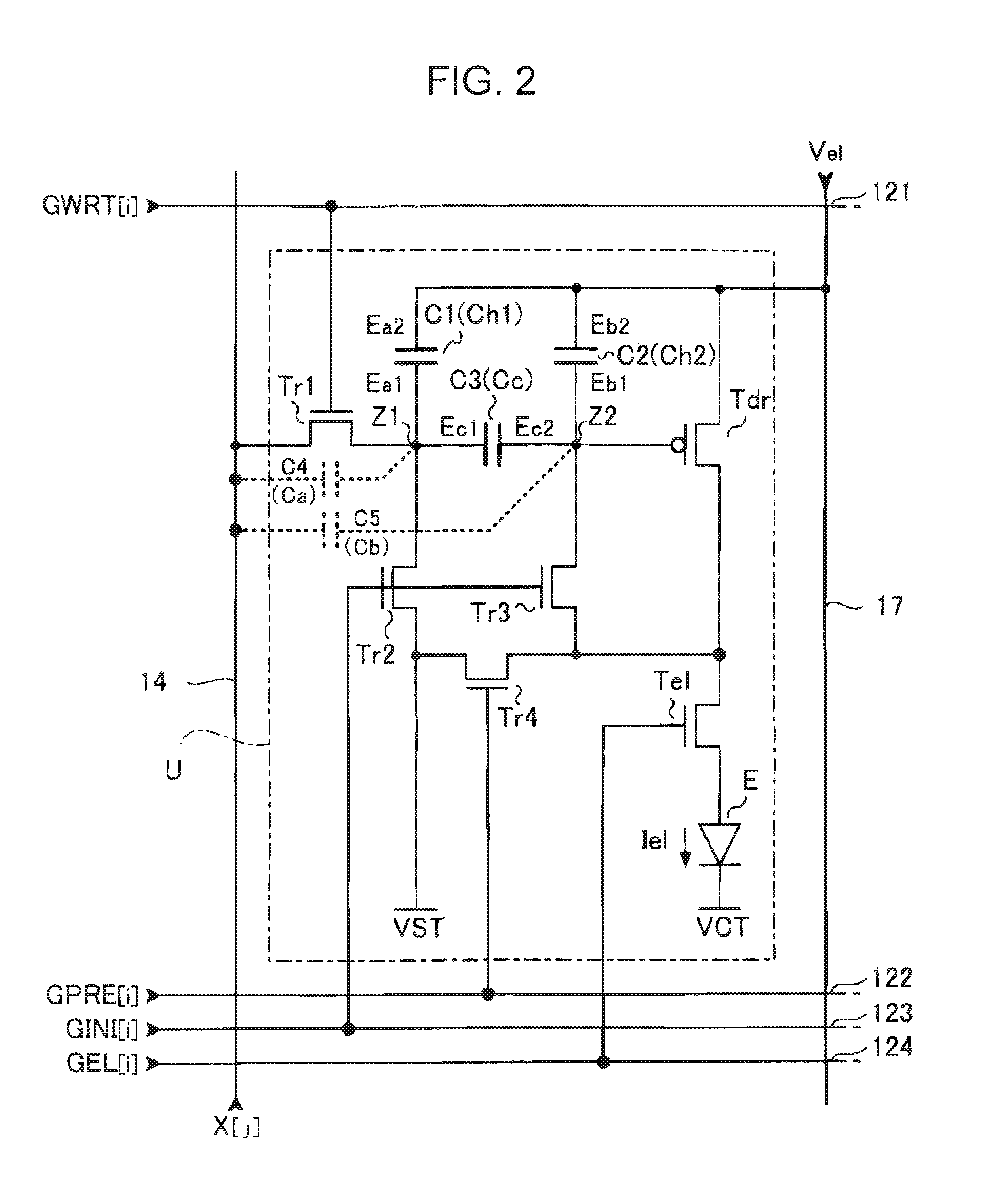
[0011]In accordance with the unit circuit described above, the first to third capacitive elements are connected in a “pi ” configuration. Therefore, providing a capacitor between a node that should hold a potential and a pixel power supply Ve1 enables a unit circuit to be relatively immune to the effects of crosstalk even when the potential of the data line varies. Moreover, since it is not necessarily required that both a compensation period and a data writing period are completed in a single horizontal scan period, a compensation operation can be performed over a plurality of horizontal scan periods. Therefore, variations in the threshold voltage can be accurately compensated, and data can be reliably written.
[0016]It is preferable that the unit circuit described above further include a power supply line that supplies a power supply potential, and the power supply line be electrically connected to the source of the drive transistor, the second electrode of the first capacitive element, and the fourth electrode of the second capacitive element. In this case, since a single power supply line supplies a power to the drive transistor and the potential of each of the first capacitive element and the second capacitive element is fixed, the structure can be simplified.
[0017]It is preferable that the unit circuit described above further include a light-emission control switching element (for example, a light-emission control transistor Te1 illustrated in FIG. 2) disposed on an electrical path between the drive transistor and the electro-optical element, the light-emission control switching element be in an on state in the driving period and be in an off state in the initialization period, the compensation period, and the data writing period. In this case, since the drive current is not supplied to the electro-optical element except for a driving period, low gray scale levels can be precisely represented, and thus an artifact where should be true black, which is a phenomenon that displays a grayish portion that should have been displayed black, can be avoided.
[0018]In the unit circuit described above, it is preferable that the first capacitive element, the second capacitive element, and the third capacitive element have substantially the same capacitance value. In this case, a maximum total capacitance can be achieved, and therefore, the effects of crosstalk can be further reduced.
[0020]In accordance with some exemplary embodiments, the first to third capacitive elements are connected in a “pi” configuration. Therefore, providing a capacitor between a node that should hold a potential and a pixel power supply Ve1 enables a unit circuit to be relatively immune to the effects of crosstalk even when the potential of the data line varies. Moreover, since it is not necessarily required that both a compensation period and a data writing period are completed in a single horizontal scan period, a compensation operation can be performed over a plurality of horizontal scan periods. Therefore, variations in the threshold voltage can be accurately compensated, and data can be reliably written.

Problems solved by technology

However, characteristics vary among transistors, and this results in a non-uniform display state for each pixel.
Crosstalk produced by such capacitive coupling is a problem for not only a single unit circuit but also between that circuit and a data line for an adjacent unit circuit.
Additionally, for known structures, since both compensation for variations in a threshold voltage and data writing are performed within a single horizontal scan period, it is difficult to obtain a sufficient period of time required for the compensation for variations in the threshold voltage.
If sufficient time is spent in compensating variations in the threshold voltage, it will be difficult to accurately write data.

Method used


Image

  • Unit circuit, electro-optical device, and electronic apparatus
  • Unit circuit, electro-optical device, and electronic apparatus
  • Unit circuit, electro-optical device, and electronic apparatus

Examples


embodiment

1. Embodiment

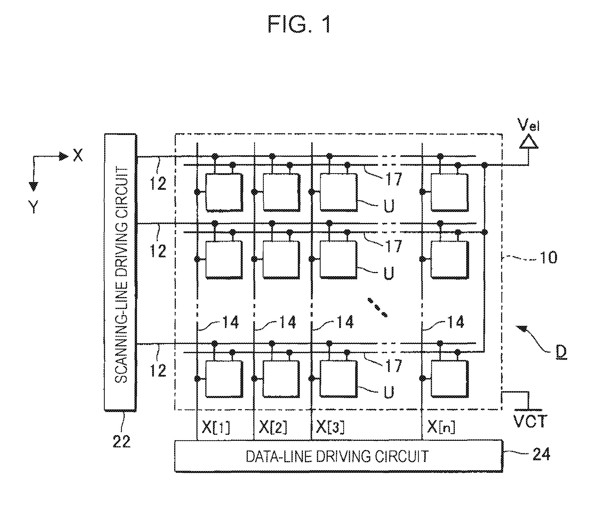
[0038]FIG. 1 is a block diagram illustrating the structure of an electronic apparatus according to an embodiment of the invention. An electronic device D illustrated in FIG. 1 is an electro-optical device (light emitting device) incorporated as an image displaying unit in one of various kinds of electronic apparatuses. The electronic device D includes an element array 10 having a plurality of unit circuits (pixel circuits) U arranged in a generally planer configuration. The electronic device D also includes a scanning-line driving circuit 22 and a data-line driving circuit 24 for driving the unit circuits U. Each of the scanning-line driving circuit 22 and data-line driving circuit 24 may be constructed of a transistor formed together with the element array 10 on a substrate or may be implemented in the form of an IC chip.

[0039]As illustrated in FIG. 1, the element array 10 is provided with m scanning lines 12 extending in the X direction and n data lines 14 extending i...

first modification

(1) First Modification

[0083]FIG. 8 illustrates a unit circuit U1. In the unit circuit U1, different signals are supplied to the gate of each of the transistors Tr2 and Tr3. In this example, a second compensation control signal GINI2[i] is supplied to the third control line 123, and a first compensation control signal GINI1[i] is supplied to a fifth control line 125. The operation of the unit circuit U1 is substantially the same as in the above-described embodiment in the initialization period P0, compensation period P1, data writing period P2, and driving period P3. As the first compensation control signal GINI1[i] and second compensation control signal GINI2[i], the compensation control signal GINI[i] described above is supplied (see FIG. 3).

[0084]Before shipping of the electronic device D, various inspections are performed. One of the inspections is to inspect a short circuit of each of the first capacitive element C1 and the third capacitive element C3. In an inspection term, the...

second modification

(2) Second Modification

[0085]FIG. 9 illustrates a unit circuit U2. The unit circuit U2 is substantially the same as the unit circuit U illustrated in FIG. 2 according to the embodiment, with the exception that the transistor Tr2 is disposed between a power-supply line that supplies the initialization potential VST and a first input terminal of the transistor Tr4. In the unit circuit U2, a supply of substantially the same signals as in the embodiment described above to the first control line 121 to the fourth control line 124 can cause the third capacitive element C3 to discharge charges stored therein in the initialization period P0, cause the second capacitive element C2 to hold the threshold voltage Vth in the compensation period P1, and cause the third capacitive element C3 to operate as a coupling capacitance and a potential corresponding to a data potential to be applied to the gate of the drive transistor Tdr and held thereby In the data writing period P2. In addition, it caus...


PUM


Abstract

A unit circuit includes an electro-optical element, a first capacitive element, a second capacitive element, a third capacitive element, a drive transistor, a first switching element, an initialization unit, and a compensation unit. The electro-optical element emits an amount of light in accordance with a magnitude of a drive current. The first capacitive element includes a first electrode and a second electrode, the first electrode is electrically connected to a first node, and the second electrode is capable of receiving a fixed potential. The second capacitive element includes a third electrode and a fourth electrode, the third electrode is electrically connected to a second node, and the fourth electrode is capable of receiving a fixed potential. The third capacitive element includes a fifth electrode and a sixth electrode, the fifth electrode is electrically connected to the first node, and the sixth electrode is electrically connected to the second node. The drive transistor includes a gate, a source, and a drain and outputs the drive current in a driving period. The gate thereof is electrically connected to the second node. In a data writing period, the first switching element is in an on state and supplies to the first node a data potential supplied via a data line. The initialization unit causes the third capacitive element to discharge charges stored therein in an initialization period. The compensation unit electrically connects the source and the drain of the drive transistor together in a compensation period.

Description

CROSS-REFERENCE TO RELATED APPLICATION[0001]This application claims priority from Japanese Patent Application No. 2006-147741 filed in the Japanese Patent Office on May 29, 2006, the entire disclosure of which is hereby incorporated by reference in its entirety.BACKGROUND[0002]1. Technical Field[0003]Embodiments of the present invention relate to a unit circuit that includes an electro-optical element, such as an organic light emitting diode (hereinafter referred to sometimes as OLED), an electro-optical device, and an electronic apparatus.[0004]2. Related Art[0005]Display devices that use an organic light emitting diode are becoming popular. One such display device includes a plurality of pixels. Each of the pixels has an organic light emitting diode and a transistor that drives the OLED. To obtain a stable uniform display state in a plane, it is necessary to cause the organic light emitting diodes in the pixels to emit the same amount of light. However, characteristics vary among ...

Claims


Application Information

Patent Timeline
Patent Type & Authority Patents(United States)
IPC IPC(8): G09G3/30G09G3/10
CPCG09G3/3233G09G2300/0819G09G2300/0852G09G2320/043G09G2320/0209G09G2320/0233G09G2300/0861G09G3/30G09G3/32
Inventor KITAZAWA, TAKAYUKIKANDA, EIJI
Owner ELEMENT CAPITAL COMMERCIAL CO PTE LTD
Why Eureka
Try Eureka