Backlight unit and display device

a backlight unit and display device technology, applied in the direction of printing, electrical apparatus casing/cabinet/drawer, instruments, etc., can solve the problems of increased manufacturing costs and heavy backlight units, and achieve the effect of uniform heat, reduced device weight, and reduced weight of backlight units and display devices having light sources

Inactive Publication Date: 2011-12-13
SONY CORP
View PDF5 Cites 21 Cited by
  • Summary
  • Abstract
  • Description
  • Claims
  • Application Information

AI Technical Summary

Benefits of technology

It is desirable to provide a device including a light source such as the above-described backlight unit, weight and costs of which can be reduced without affecting the heat uniformity of the whole device.
According to the configuration, the base member, on which the light source substrate having the light source is mounted, is formed by processing the sheet metal and includes the plurality of groove portions extending in the lengthwise direction of the light source substrate formed at the predetermined intervals and the plurality of planes between the groove portions on which the light source substrates facing the display panel are formed respectively. Accordingly, the weight of the device is reduced. Further, the heat pipe is provided in the lengthwise direction of the light source substrate on the rear side of the respective planes of the base member using a level difference of the groove portion. Therefore, generated heat due to the light emission in the light source of the light source substrate is transmitted to the heat pipe through the base member. Particularly, the heat is transmitted from a high-temperature central part of the heat pipe to the periphery portion. As a result, the heat of the whole backlight unit may be uniform.
According to the configuration, the base member, on which the light source substrate having the light source is mounted, is formed by processing the sheet metal and includes the plurality of groove portions extending in the lengthwise direction of the light source substrate formed at the predetermined intervals and the plurality of planes between the groove portions on which the light source substrates facing the display panel are formed respectively. Accordingly, the weight of the device is reduced. Further, the heat pipe is provided in the lengthwise direction of the light source substrate on the rear side of the respective planes of the base member using a level difference of the groove portion. Therefore, generated heat due to the light emission in the light source of the light source substrate is transmitted to the heat pipe through the base member. Particularly, the heat is transmitted from a high-temperature central part of the heat pipe to the periphery portion. As a result, the heat of the whole display device may be uniform.
According to the embodiments of the present invention, weight of the backlight unit and display device having the light source is reduced, while keeping the heat thereof uniform, and therefore material costs can be reduced. Moreover, since the base member is made of plate-shaped material and therefore can be processed readily, the costs for assembly and manufacturing can be reduced.

Problems solved by technology

As a result, the backlight unit may become heavy and costs for the manufacture may increase.

Method used


Image

  • Backlight unit and display device
  • Backlight unit and display device
  • Backlight unit and display device

Examples


Embodiment Construction

Embodiments of the present invention are hereinafter described with reference to the accompanied drawings. In the following embodiments, a display device according to an embodiment of the present invention is applied to a transmissive liquid crystal display device having a backlight unit.

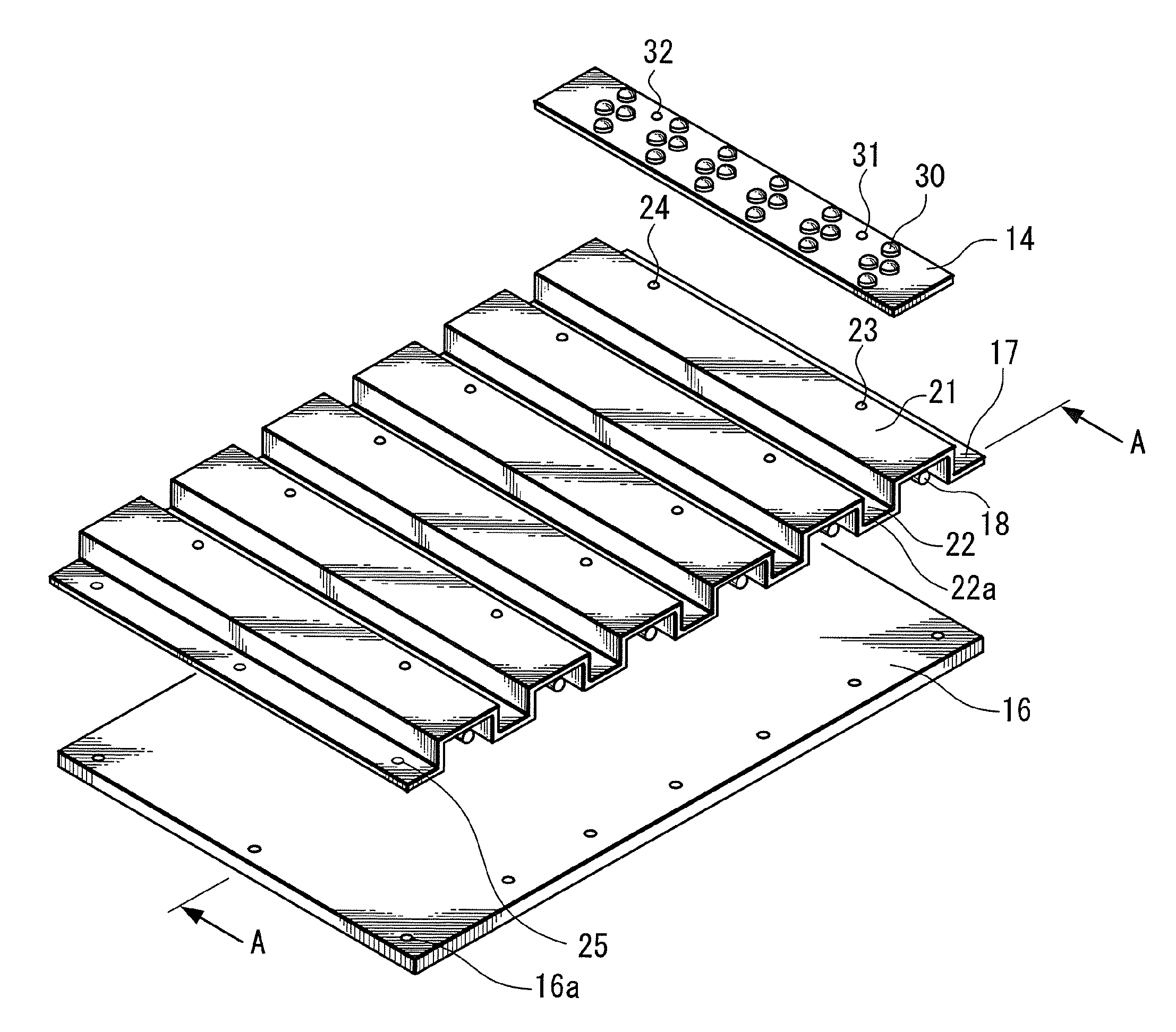
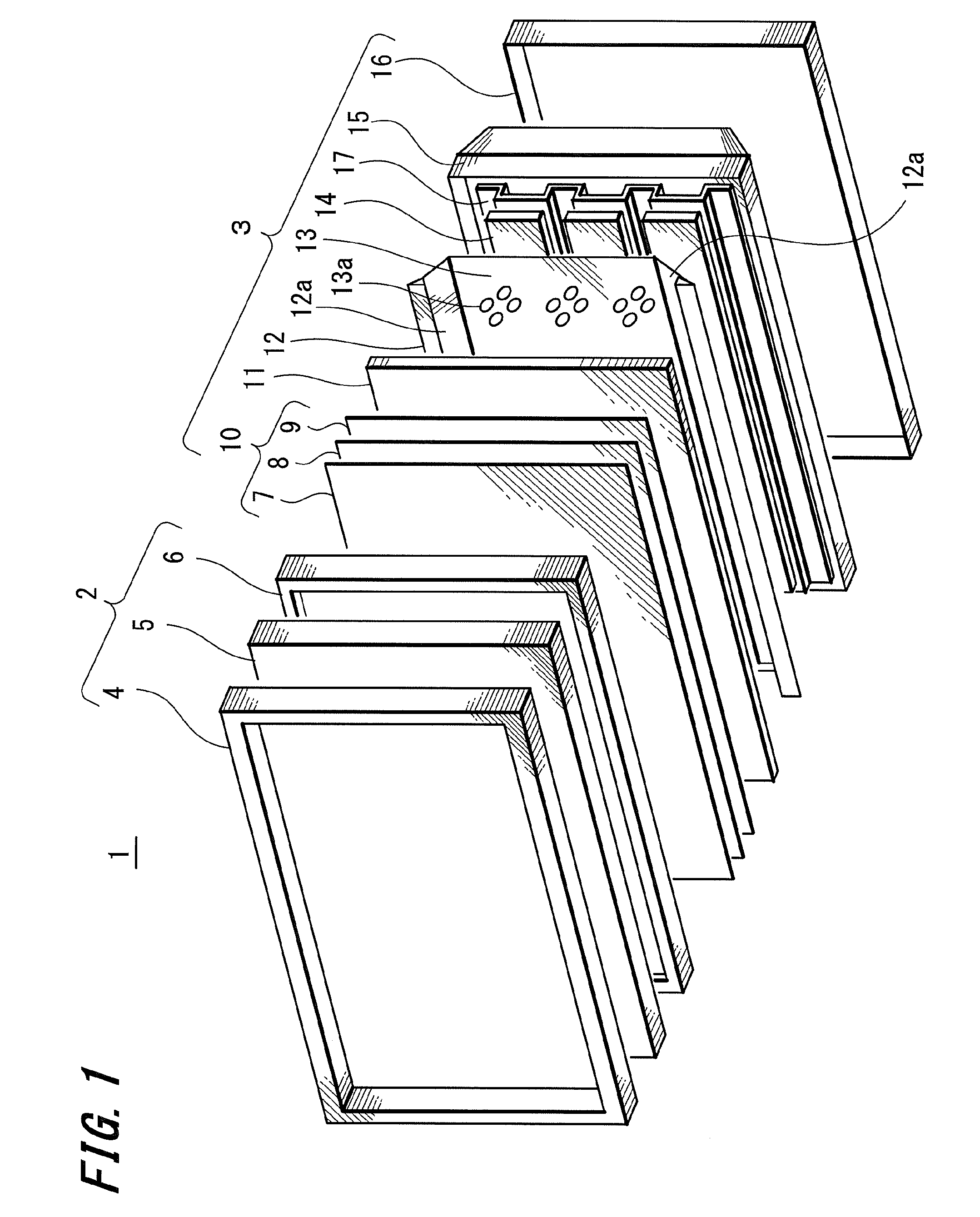
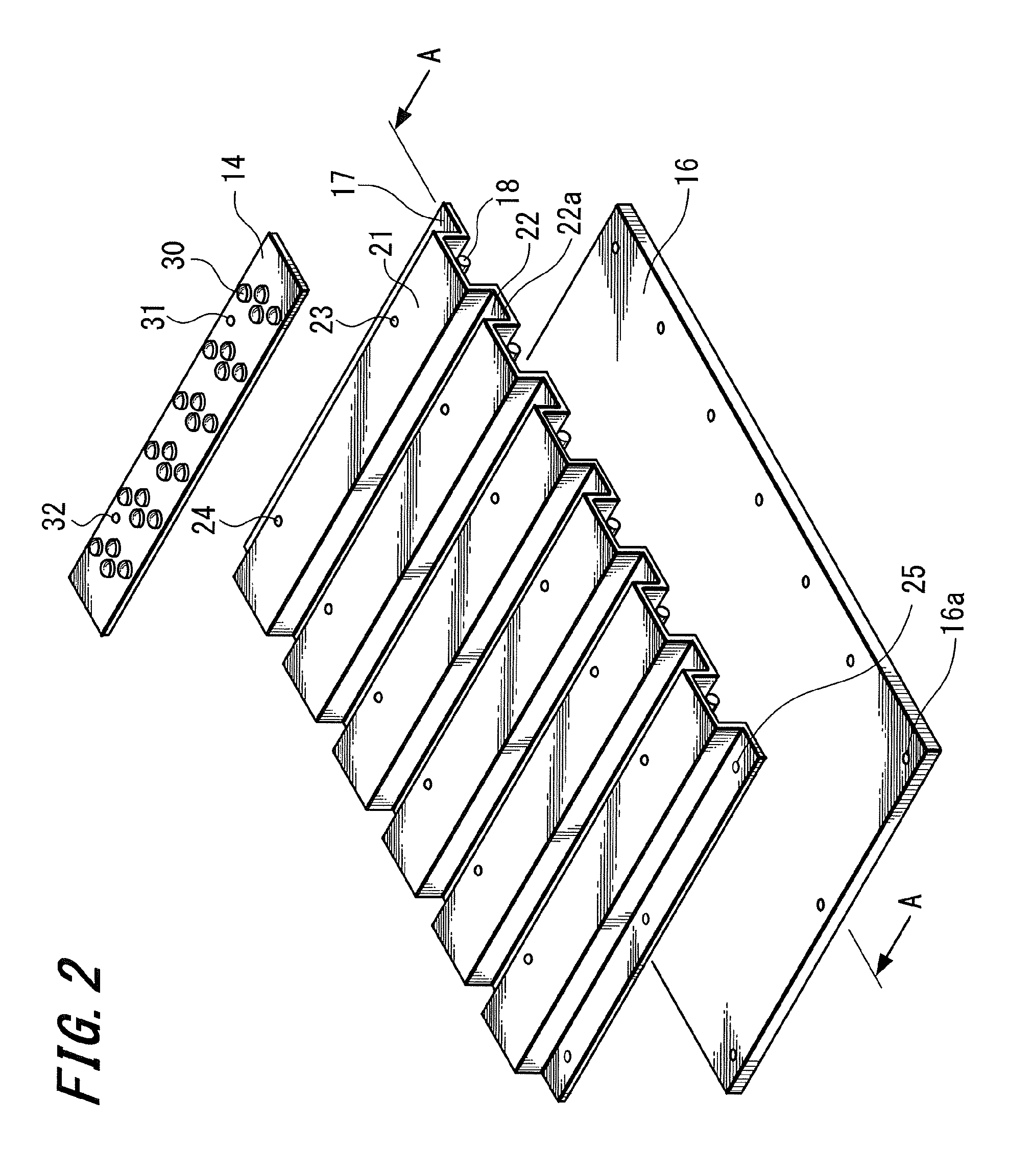
FIG. 1 is an exploded perspective view of the liquid crystal display device that is an example of the display device according to the embodiment of the present invention.

As shown in FIG. 1, a liquid crystal display device 1 as an example of the display device includes a liquid crystal panel unit 2 and a backlight unit (backlight device) 3 assembled at the rear of the liquid crystal panel 2 to apply display light.

The liquid crystal panel unit 2 includes a front frame 4, a liquid crystal panel 5, and a frame-shaped middle chassis 6 serving as a support mechanism for an optical sheet. In the liquid crystal panel unit 2, an outer periphery of the liquid crystal panel 5 is mounted on the groove formed in...


PUM


Abstract

A backlight unit illuminating the rear of a transmissive display panel with light includes a light source substrate, a base member, and a heat pipe. The light source substrate has a light source and faces the rear of the display panel. The base member is made of sheet metal, on which the light source substrate is mounted, and fixed to the rear of a chassis of the backlight unit. The heat pipe is attached to the base member and receives heat generated in the light source through the base member. The base member includes a plurality of groove portions extending in a lengthwise direction of the light source substrate formed at predetermined intervals and a plurality of planes on which the light source substrates facing the display panel are formed respectively. The heat pipe is provided in the lengthwise direction of the light source substrate under each of the planes.

Description

CROSS REFERENCES TO RELATED APPLICATIONSThe present invention contains subject matter related to Japanese Patent Application JP 2007-003855 filed in the Japanese Patent Office on Jan. 11, 2007, the entire contents of which being incorporated herein by reference.BACKGROUND OF THE INVENTION1. Field of the InventionThe present invention relates to a backlight unit and a display device, and more particularly to the backlight unit and the display device suitable for application to a liquid crystal display device or the like having a large display screen.2. Description of the Related ArtLiquid crystal display devices have a large display screen and reduced weight, thickness and power consumption as compared to a CRT (Cathode-Ray Tube), and accordingly have been used widely for a television receiver and various displays in addition to a light-emitting display such as a PDP (Plasma Display Panel), for example.A liquid crystal display device includes a liquid crystal sealed between two trans...

Claims


Application Information

Patent Timeline
Patent Type & Authority Patents(United States)
IPC IPC(8): F21V8/00
CPCG02F1/133603G02F2001/133628G02F1/133628H05K7/2099G02F1/1335
Inventor MARUYAMA, NAOKI
Owner SONY CORP
Why Eureka
Try Eureka