High frequency epidural neuromodulation catheter for effectuating RF treatment in spinal canal and method of using same

a neuromodulation catheter and high-frequency technology, applied in the field of medical devices, can solve the problems of tissue to heat, thermal lesion of the medial branch nerve, worsening pain,

Inactive Publication Date: 2011-12-13
BETTS ANDRES
View PDF28 Cites 37 Cited by
  • Summary
  • Abstract
  • Description
  • Claims
  • Application Information

AI Technical Summary

Benefits of technology

[0014]The catheter apparatus of the present invention is envisioned as one capable of accessing the epidural space, similar to the SCS, and directed to the desired DRG using standard fluoroscopic monitoring technique. The cannula of the catheter apparatus is entirely shielded with non-conducting material, except the distal 10 mm active tip, which is blunt and curved. This is similar to the design of a standard radiofrequency cannula, but of much greater flexibility and length. Once positioned over the DRG by fluoroscopic guidance, the device may be attached to a standard radiofrequency generator, and 50 Hz sensory stimulating current may be applied. The sensory stimulation is utilized to make small adjustments in the cannula position, thereby obtaining precise physiologic localization of the cannula tip over the desired DRG. The cannula tip may be curved to allow steerage, and is blunt to reduce risk of entering the spinal thecal sac, or cause direct nerve damage to the DRG. The cannula is also constructed to accept a standard radiofrequency probe that typically have a built in thermistor to measure temperature at the tip in real time, and to deliver pulsed radiofrequency energy. The cannula is designed to allow radiofrequency energy to be applied directly to the DRG via the epidural route. This technique may be performed in instances where the transforaminal approach is not feasible, or may even prove to become the preferred approach depending on the clinical results.

Problems solved by technology

A probe whose tip emits radiofrequency energy is inserted into the hollow cannula, and causes tissue to heat around the un-insulated cannula tip, resulting in a thermal lesion to the medial branch nerves.
Unfortunately, thermal lesions to spinal nerve roots or other painful peripheral nerves often result in a worsening of the pain due to a thermal neuritis.
However, spinal stenosis, post-operative scarring, or other conditions may make the DRG inaccessible via a transforaminal approach; in such a setting, there is no currently available device or technique for performing RF treatment.
This procedure with the SCS lead and generator has costs in excess of $20,000, and many patients do not desire a foreign body to be surgically implanted.
Furthermore, SCS only serves to disrupt the pain signals by creating a competing parasthesia signal, which can be unpleasant or ineffective for some patients, rather than creating a lesion on the nerves which actually blocks the pain signals from being transmitted.
However, the analgesic effect of epidural anesthesia is only of a temporary nature.
Furthermore, it is impractical and inconvenient to provide repeated epidural injections to a patient for use as a long-term pain management solution.

Method used


Image

  • High frequency epidural neuromodulation catheter for effectuating RF treatment in spinal canal and method of using same
  • High frequency epidural neuromodulation catheter for effectuating RF treatment in spinal canal and method of using same
  • High frequency epidural neuromodulation catheter for effectuating RF treatment in spinal canal and method of using same

Examples


Embodiment Construction

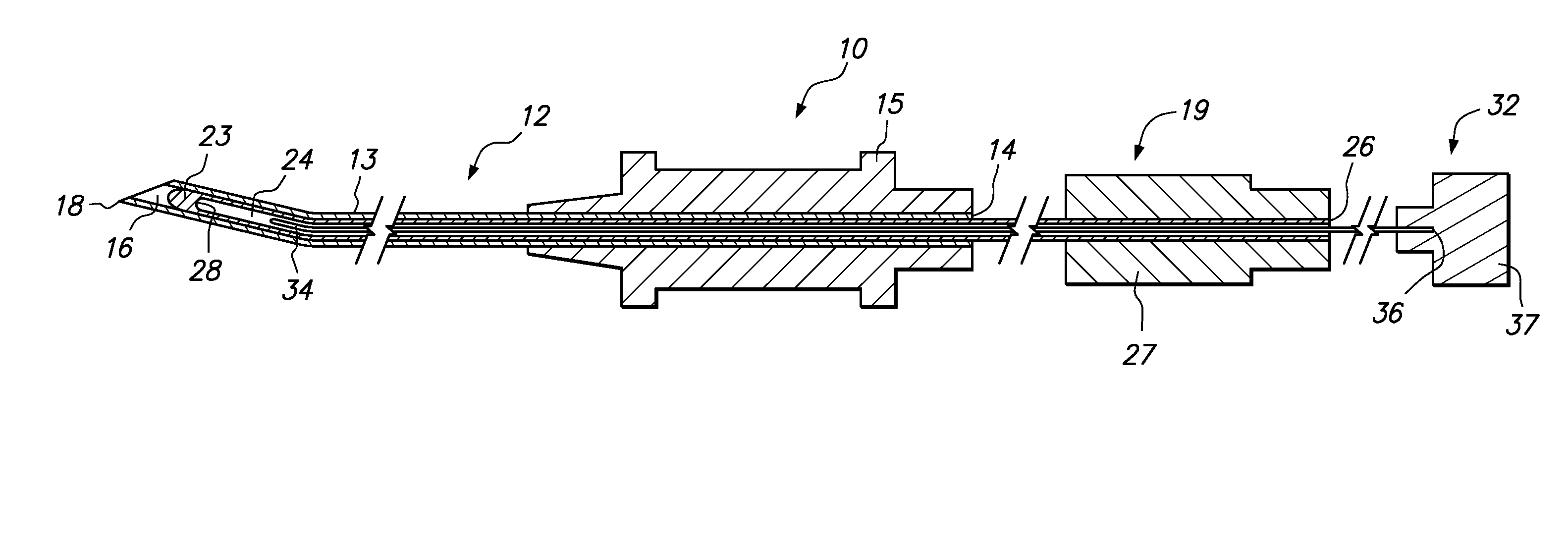
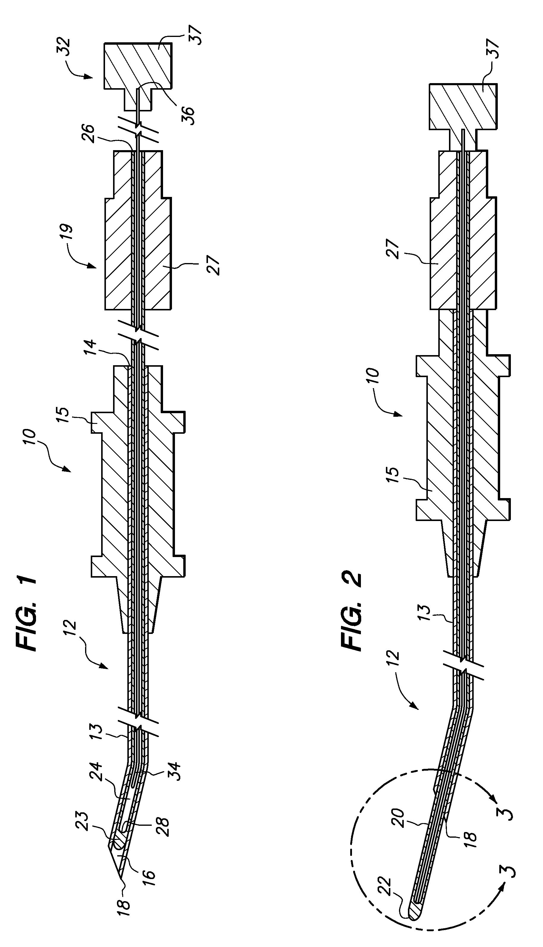
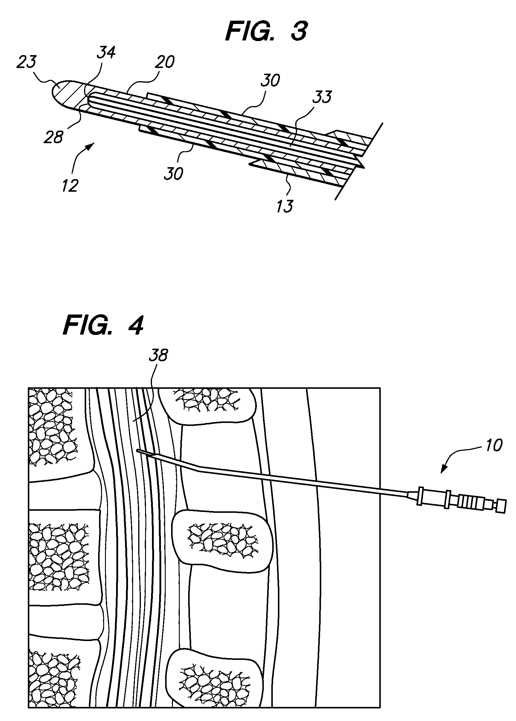
[0021]Referring now to the drawings, which are illustrative of one embodiment of the present invention only and are not for purposes of limiting the same, FIG. 1 shows a partially assembled catheter apparatus 10 constructed in accordance with the present invention. As shown in FIGS. 1 and 2, the catheter apparatus 10 includes a needle assembly 12 having an elongate needle 13. The needle 13 of the needle assembly 12 has an open proximal end 14 which is defined within one end of an enlarged needle hub 15 of the needle assembly 12, the needle 13 being partially disposed with the needle hub 15 in the manner shown in FIGS. 1 and 2. The needle hub 15 is configured to be easily graspable to allow for the insertion of the needle 13 of the needle assembly 12 to a desired treatment site, as will be described in more detail below. The needle 13 of the needle assembly 12 further includes a hollow lumen 16 and an open distal end 18. The distal end 18 of the needle 13 is itself defined by a sharp...


PUM


Abstract

A catheter apparatus includes a hollow needle having an open, sharpened tip at its distal end. A cannula is telescopically disposed within the needle. The cannula has a closed, blunt tip at its distal end, a hollow lumen, and an open proximal end. The cannula is made of a flexible metal material and has an insulating material covering except at its distal portion defining the distal end. A metallic wire capable of transmitting radio frequency (RF) energy is telescopically disposed within the cannula. The cannula lumen has a seating surface for accommodating the distal end of the wire. The cannula distal end is capable of extending beyond the needle so that the blunt tip may be seated in a critical treatment region in a patient's spinal canal without damaging any nerves. A method of treating a patient's pain includes a step of inserting the catheter apparatus into a critical treatment region in the spinal canal of the patient. Once the needle is located near the treatment region, the cannula is advanced until the blunt tip extends beyond the needle's distal end. RF energy is then transmitted through the wire, the cannula's blunt tip, and to the treatment region.

Description

CROSS-REFERENCE TO RELATED APPLICATIONS[0001]This application claims the benefit of U.S. Provisional Application No. 60 / 802,685, filed on May 23, 2006, the teachings of which are expressly incorporated by reference.STATEMENT RE: FEDERALLY SPONSORED RESEARCH / DEVELOPMENT[0002]Not ApplicableBACKGROUND OF THE INVENTION[0003]1. Field of the Invention[0004]The present invention relates generally to medical devices, and more particularly to an improved catheter for providing radio frequency (RF) treatment to a prescribed region within the spinal canal of a patient. Further in accordance with the present invention, there is provided a method for utilizing such a catheter.[0005]2. Background Art[0006]Radiofrequency (RF) treatment of pain has a long history in the field of pain management, and has been extensively utilized for the treatment of spine pain due to facet joint origin, in particular. Typically, a hollow cannula whose tip is sharp may be inserted percutaneously and positioned under...

Claims


Application Information

Patent Timeline
Patent Type & Authority Patents(United States)
IPC IPC(8): A61B18/14
CPCA61B18/1477A61B18/148A61B18/1492A61B2018/00083A61B2018/00196A61B2018/00434A61B2018/0044A61B2018/1475
Inventor BETTS, ANDRES
Owner BETTS ANDRES
Why Eureka
Try Eureka