Apparatus, circuitry, signals, probes and methods for cleaning and/or processing with sound

a technology of circuitry and sound, applied in the direction of mechanical vibration separation, cleaning using liquids, generators/motors, etc., can solve the problems of modern jet engine turbine blades which can fracture, the feature size of the semiconductor wafer is extremely small, etc., to prevent low frequency resonance and eliminate possible resonances

Inactive Publication Date: 2011-12-13
PUSKAS WILLIAM L
View PDF98 Cites 3 Cited by
  • Summary
  • Abstract
  • Description
  • Claims
  • Application Information

AI Technical Summary

Benefits of technology

[0036]The present invention concerns the applied uses of ultrasound energy, and in particular the application and control of ultrasonics to clean and process parts within a liquid. Generally, in accord with the invention, one or more ultrasound generators drive one or more ultrasound transducers, or arrays of transducers, coupled to a liquid to clean and / or process the part. The liquid is preferably held within a tank; and the transducers mount on or within the tank to impart ultrasound into the liquid (examples of transducers that mount within the tank are immersible shoe box type transducers often called immersibles or submersibles, tube or cylinder shaped submersible transducers driven at one or both ends, often called push pull transducers and tube transducers). In this context, the invention is particularly directed to one or more of the following aspects and advantages:
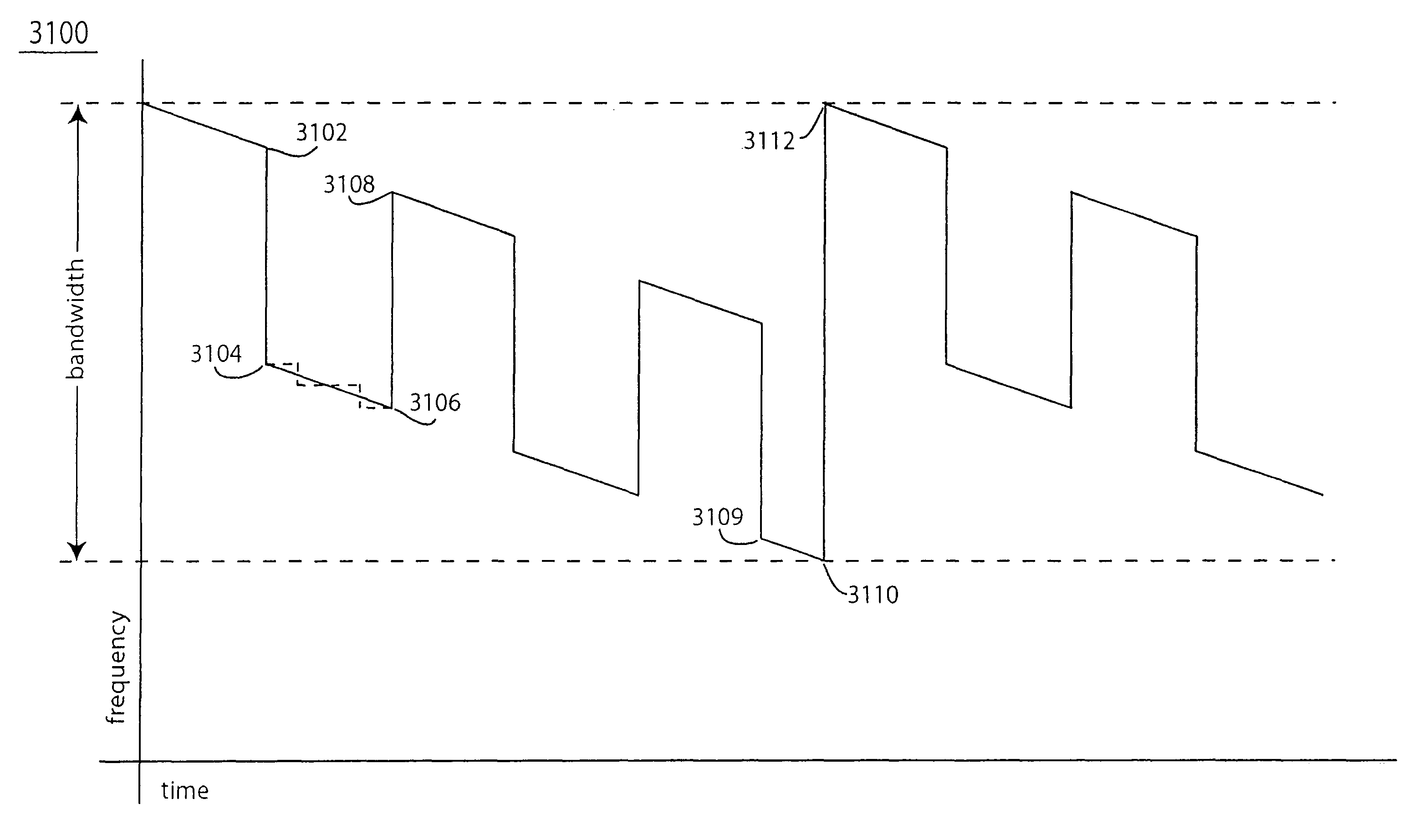
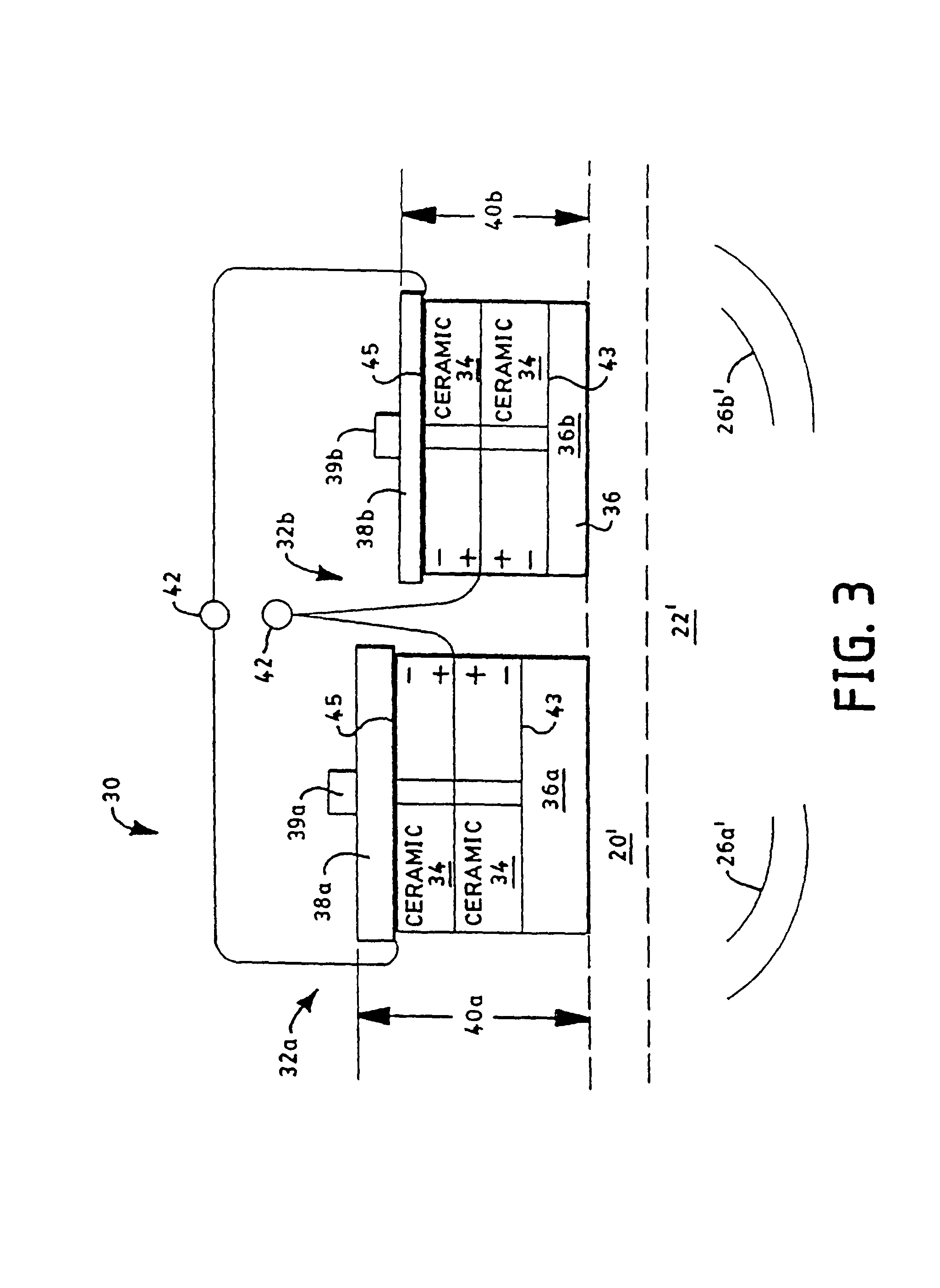
[0184]In another embodiment of the invention a new wide range multiple frequency transducer that will operate at regions in each area of the wide frequency range from ultrasonic to microsonic to megasonic is a sandwich type transducer. The unique concept that makes megasonics operation practical in this sandwich type transducer is that the thickness of each piezoelectric ceramic is designed such that an integer number of half wavelengths of sound exist in the ceramic at the megasonics frequency; and the back mass and the front mass with its bonded surface each contain an integer number of half wavelengths plus one quarter of a wavelength at the megasonics frequency. Good design practice calls for the clamping bolt or other clamping assembly to be recessed from the outer surface of the back mass and / or from the radiating surface of the front mass so its load bearing surface or surfaces are at nodal points of the megasonics half wavelengths within the front mass and / or the back mass. Another unique feature of this inventive sandwich type transducer structure (Langevin type structure) when operated at megasonics frequencies is the heat dissipating ability of the stacked structure. This allows reliable off resonance operation of the transducer in ranges around the megasonics center frequency, which allows sweeping in the megasonics frequency range. The inventor has found that sweeping megasonics has advantages over the state of the art single frequency megasonics. The collimated megasonic characteristic of the prior art is reduced by sweeping megasonics and the process efficiency is improved because there is less absorption of sound energy when sweeping compared to prior art single frequency megasonics.

Problems solved by technology

By way of example, one delicate part is a semiconductor wafer which has extremely small features and which is easily damaged by cavitation implosion.
Another delicate part is a modern jet engine turbine blade which can fracture if excited into resonant vibration.

Method used


Image

  • Apparatus, circuitry, signals, probes and methods for cleaning and/or processing with sound
  • Apparatus, circuitry, signals, probes and methods for cleaning and/or processing with sound
  • Apparatus, circuitry, signals, probes and methods for cleaning and/or processing with sound

Examples


Embodiment Construction

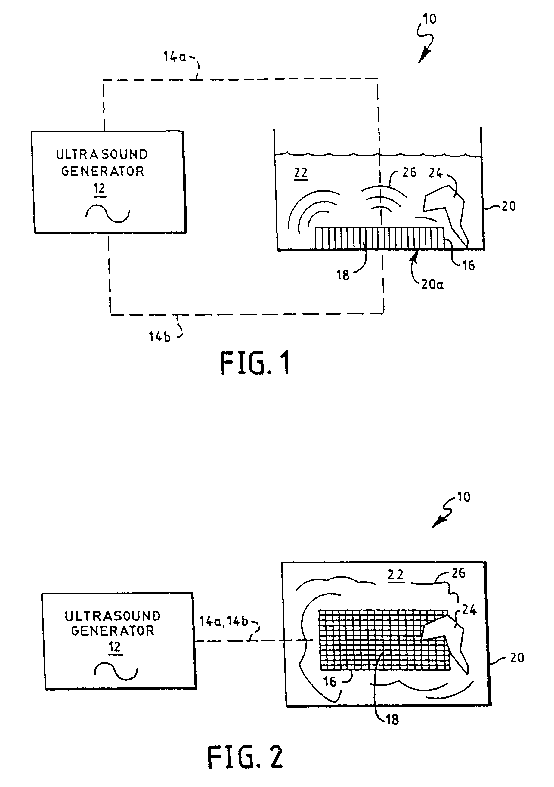
[0286]FIGS. 1 and 2 show schematic side and top views, respectively, of an ultrasound processing system 10 constructed according to the invention. An ultrasound generator 12 electrically connects, via electrical paths 14a, 14b, to an ultrasound transducer 16 to drive the transducer 16 at ultrasound frequencies above about 18 khz, and usually between 40 khz and 350 khz. Though not required, the transducer 16 is shown in FIG. 1 as an array of transducer elements 18. Typically, such elements 18 are made from ceramic, piezoelectric, or magnetostrictive materials which expand and contract with applied voltages or current to create ultrasound. The transducer 16 is mounted to the bottom, to the sides, or within the ultrasound treatment tank 20 through conventional methods, such as known to those skilled in the art and as described above. A liquid 22 fills the tank to a level sufficient to cover the delicate part 24 to be processed and / or cleaned. In operation, the generator 12 drives the t...


PUM

PropertyMeasurementUnit
time durationaaaaaaaaaa
frequenciesaaaaaaaaaa

Abstract

The invention utilizes single and multiple frequency ultrasound generators driving single and multiple frequency resonant and harmonic transducer arrays at frequencies into the megasonic range. Generator signals that increase cavitation efficiency improve the performance of the cleaning, microbiological inactivation, sonochemistry or processing systems.

Description

RELATED APPLICATIONS[0001]The subject application is a continuation-in-part of commonly owned and co-pending U.S. patent application Ser. No. 11 / 177,750 filed Jul. 8, 2005, which is expressly incorporated herein by reference. This application has a priority claim that is detailed below.[0002]Priority claim of U.S. patent application Ser. No. 11 / 177,750: U.S. patent application Ser. No. 11 / 177,750 filed Jul. 8, 2005, entitled “Apparatus, Circuitry, Signals, Probes and Methods for Cleaning and / or Processing with Sound”, (now U.S. Pat. No. 7,336,019, granted Feb. 26, 2008), is a continuation-in-part of co-pending U.S. patent application Ser. No. 11 / 173,468 which is expressly incorporated herein by reference. This application has a priority claim that is detailed below.[0003]Priority claim of U.S. patent application Ser. No. 11 / 173,468: U.S. patent application Ser. No. 11 / 173,468 filed Jul. 1, 2005, entitled “Organism Inactivation Method and System”, now abandoned is a continuation-in-p...

Claims


Application Information

Patent Timeline
Patent Type & Authority Patents(United States)
IPC IPC(8): B08B3/12H02N2/00
CPCB01J19/10B06B1/0284B06B2201/71
Inventor PUSKAS, WILLIAM L.
Owner PUSKAS WILLIAM L
Why Eureka
Try Eureka