Coherent optical receiver and adjustment method thereof

a receiver and coherent technology, applied in optics, electromagnetic transmission, instruments, etc., can solve the problems of insufficient information quantity, inability to provide information on the intensity of signal light, and various distortions of input signal light, and achieve good reception characteristics

Active Publication Date: 2011-12-13
NEC CORP
View PDF7 Cites 11 Cited by
  • Summary
  • Abstract
  • Description
  • Claims
  • Application Information

AI Technical Summary

Benefits of technology

[0018]Accordingly, an object of the present invention is to provide a coherent optical receiver that can achieve good reception characteristics even if input signal light is suffering various waveform distortions, as well as a method for adjusting the receiver.
[0021]According to the present invention, it is possible to achieve good reception characteristics even if input signal light is suffering various waveform distortions.

Problems solved by technology

Optical communication using a two-intensity-level signal is easy to implement but is not always the best in performance.
Although the excellence in reception sensitivity has no longer been regarded as an advantage large enough to compensate for the structural complexity since optical amplifiers became commercially practical, the coherent optical transmission schemes still continue to draw attention from different points of view.
In this case, only information on the intensity of the signal light, provided from an OE converter, is not sufficient in terms of information quantity.
Moreover, as the signal rate increases, more technical problems arise with the fact that a serial signal, in which signals are simply time-division-multiplexed, is processed directly.
As yet, the reported results of experimental studies have not exceeded the feasibility verification level because, in part, of a performance problem with electronic parts for waveform correction processing and decoding processing.
However, in a coherent optical receiver, input is signal light suffering various waveform distortions or signal light in which individual bits have different amounts of energy.
However, if waveform distortion occurs and, as a result, the signal amplitude varies with systems, then it is necessary to perform optimization for each case.
In cases of coherent optical receivers used for the purpose of compensating for signal waveform distortion through digital signal processing at an electrical stage, there is a possibility that input signal light has various distortions.
That is, if the receiver is optimized suitably to a state of small waveform distortion, a signal input to the AD converter, in an area where the waveform distortion is large, exceeds the input dynamic range of the AD converter, resulting in accurate demodulation being impossible.
On the other hand, if the receiver is optimized suitably to waveforms having large distortions, only part of the ability of the AD converter is used when signal light suffering small waveform distortion is input, resulting in the reception performance being degraded.

Method used


Image

  • Coherent optical receiver and adjustment method thereof
  • Coherent optical receiver and adjustment method thereof
  • Coherent optical receiver and adjustment method thereof

Examples


Embodiment Construction

1. Structure

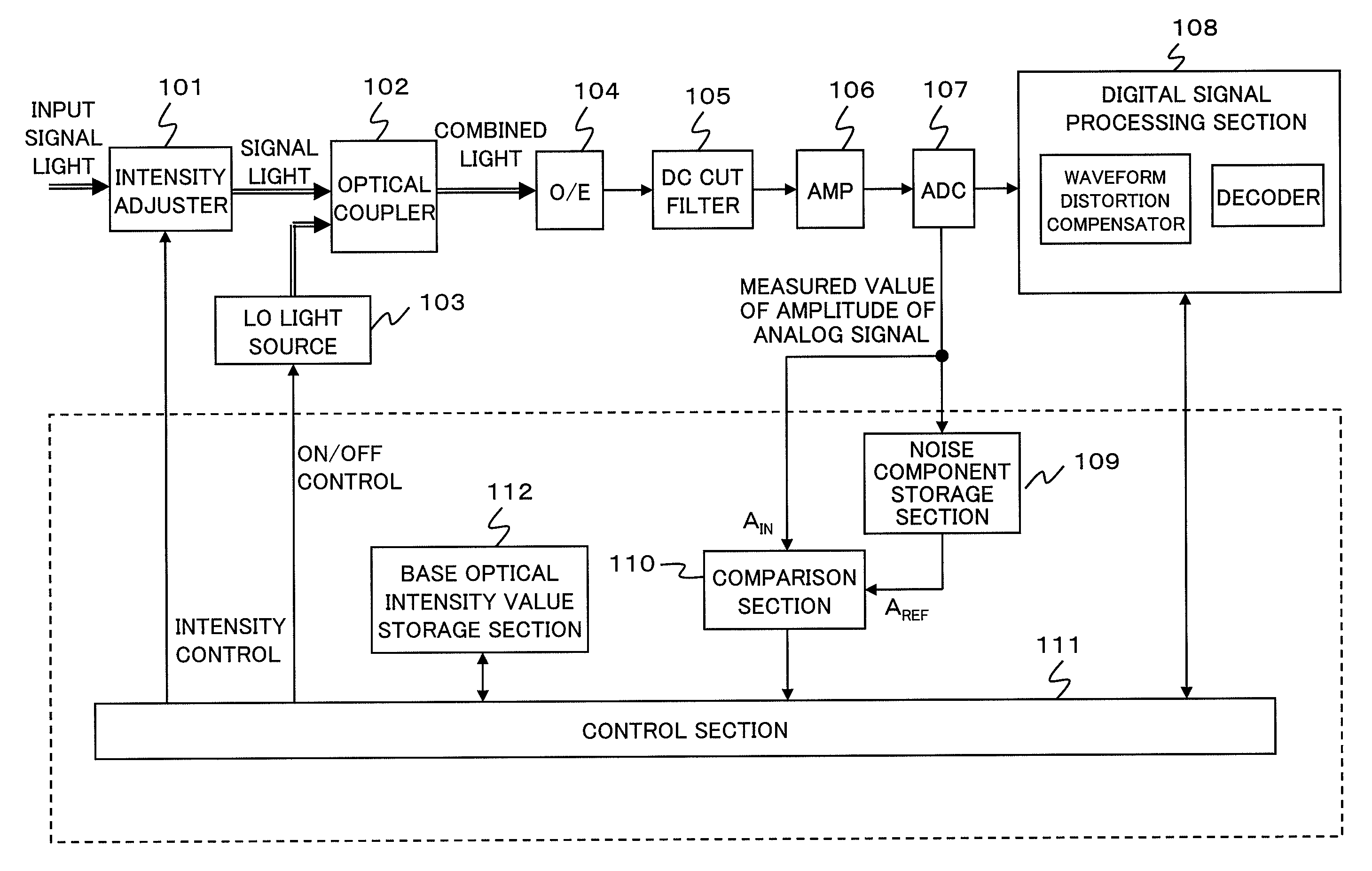
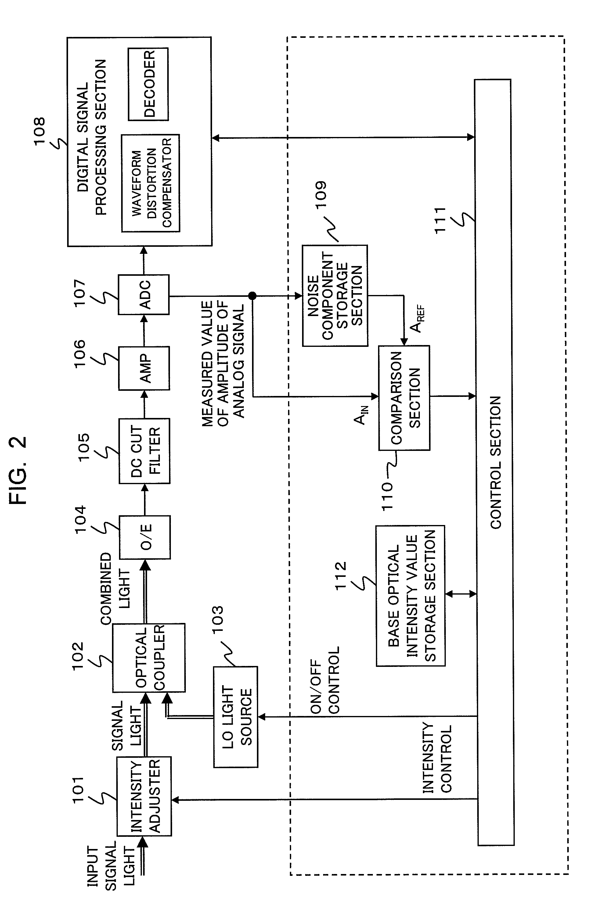
[0030]FIG. 2 is a block diagram showing a functional structure of a coherent optical receiver according to an exemplary embodiment of the present invention. An intensity adjuster 101 adjusts the intensity of input signal light that has arrived at the coherent optical receiver after passing through an optical transmission line such as an optical fiber line, and outputs the signal light to an optical coupler 102. The optical coupler 102 combines this signal light with local-oscillator (LO) light input from a LO light source 103 and outputs combined light to an optical-to-electrical (OE) converter 104.

[0031]The OE converter 104 converts the received combined light into an electrical signal and outputs the electrical signal to a direct-current (DC) cut filter 105. After a DC component is removed from this electrical signal by the DC cut filter 105, the electrical signal is amplified by an amplifier 106 and then input to an analog-to-digital (AD) converter 107. The amplifier ...


PUM

PropertyMeasurementUnit
optical intensityaaaaaaaaaa
electricalaaaaaaaaaa
electricallyaaaaaaaaaa

Abstract

In a coherent optical receiver, a light intensity value of signal light providing an optimum reception state is determined when ideal signal light free from waveform distortion is used as the signal light in a state where local-oscillator light is turned on. A first amplitude value of an analog electrical signal corresponding to the signal light is stored in a storage section, wherein the first amplitude value is obtained at a time when the ideal signal light of the light intensity value determined is used as the signal light in a state where the local-oscillator light is turned off. Light intensity of the signal light is determined so as to make a second amplitude value equal to the first amplitude value, wherein the second amplitude value is an amplitude value of the analog electrical signal which is obtained at a time when actual signal light is used as the signal light in a state where the local-oscillator light is turned off.

Description

BACKGROUND OF THE INVENTION[0001]1. Field of the Invention[0002]This application is based upon and claims the benefit of priority from Japanese Patent Application No. 2008-055716, filed on Mar. 6, 2008, the disclosure of which is incorporated herein in its entirety by reference.[0003]The present invention relates to an optical transmission system and, more particularly, to a coherent receiver and a method for adjusting the coherent receiver.[0004]2. Description of the Related Art[0005]Optical transmission systems, which use optical fiber as a transmission medium, play an essential role in trunk communication networks, for their excellent long-distance and large-capacity transmission performances. In many of optical transmission systems provided for practical use, a signal to be transmitted is superposed onto signal light by intensity modulation. Specifically, a digital binary (I / O) signal is assigned light ON / OFF. In part of the latest optical transmission systems in which the trans...

Claims


Application Information

Patent Timeline
Patent Type & Authority Patents(United States)
IPC IPC(8): H04B10/06H04B10/516G02F2/00H04B10/07H04B10/2507H04B10/61
CPCH04B10/61H04B10/616H04B10/65
Inventor ITO, TOSHIHARU
Owner NEC CORP
Why Eureka
Try Eureka