Quick change knife blade assembly for a tape roll dispensing cartridge assembly of a case sealing machine

a sealing machine and tape roll technology, applied in the field of quick change knife blade assembly, can solve the problems of inordinate time-consuming procedures, high cost of employing maintenance personnel, and considerable time-consuming for maintenance personnel

Active Publication Date: 2011-12-20
SIGNODE IND GRP
View PDF7 Cites 17 Cited by
  • Summary
  • Abstract
  • Description
  • Claims
  • Application Information

AI Technical Summary

Benefits of technology

[0005]However, when the pin plate is manually moved to a depressed position, against the biasing forces of the spring members operatively associated with the pin plate, the mounting pins are moved axially so as to effectively remove the second relatively large diameter portions of the mounting pins from the relatively enlarged circular portions of the key-hole slots defined within the knife blade or cutting member and to thereby permit the first relatively small diameter portions of the mounting pins to now be disposed within the relatively enlarged circular portions of the key-hole slots of the knife blade or cutting member and therefore be aligned with the relatively narrow elongated slot portions of the key-hole slots of the knife blade or cutting member. Accordingly, the knife blade or cutting member may simply be removed from the mounting plate as a result of the first relatively small diameter portions of the mounting pins effectively passing through the relatively narrow elongated slot portions of the key-hole slots defined within the knife blade or cutting member, and while, for example, the pin plate is maintained at its depressed position against the biasing forces of the spring members, a new or fresh knife blade or cutting member may simply be mounted upon the mounting plate. When the pin plate is then manually released, the biasing forces of the spring members will cause the pin plate to be returned to its original biased position so as to effectively force the second relatively large diameter portions of the mounting pins to re-enter the relatively enlarged circular portions of the key-hole slots defined within the new or fresh knife blade or cutting member so as to fixedly retain the new or fresh knife blade or cutting member upon the mounting plate.

Problems solved by technology

Accordingly, when, for example, the knife blade assemblies need to be replaced, not only is it expensive to employ such maintenance personnel, but just as importantly, such procedures are inordinately time-consuming in that it usually takes a considerable amount of time for the maintenance personnel to arrive and replace the knife blade assemblies, during which time the carton or case sealing production line needs to be stopped and effectively shut down.
This obviously results in a loss of valuable production or carton or case flow-through time which adds to the operative expenses of the overall carton or case sealing manufacturing operations.

Method used


Image

  • Quick change knife blade assembly for a tape roll dispensing cartridge assembly of a case sealing machine
  • Quick change knife blade assembly for a tape roll dispensing cartridge assembly of a case sealing machine

Examples


Embodiment Construction

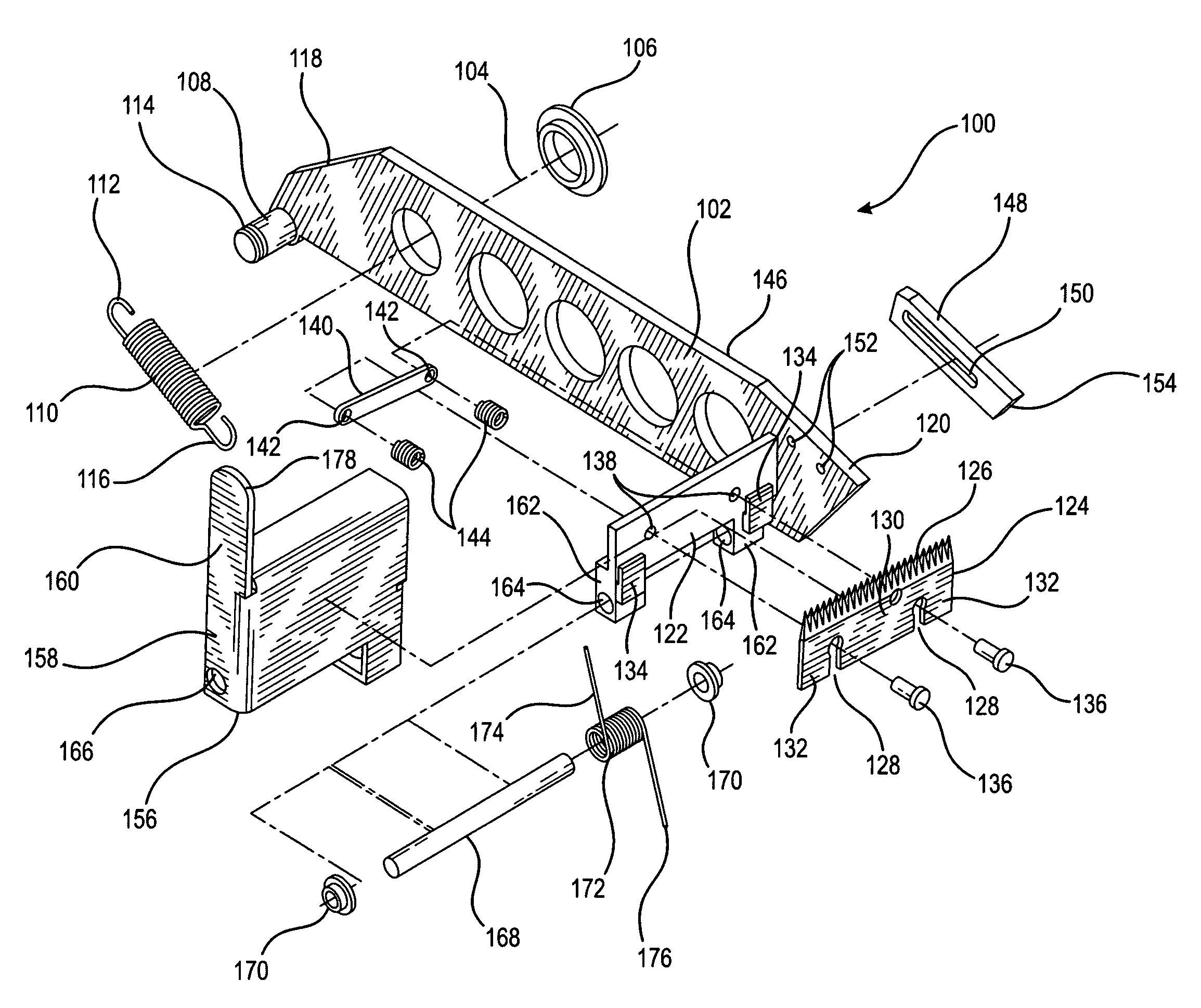
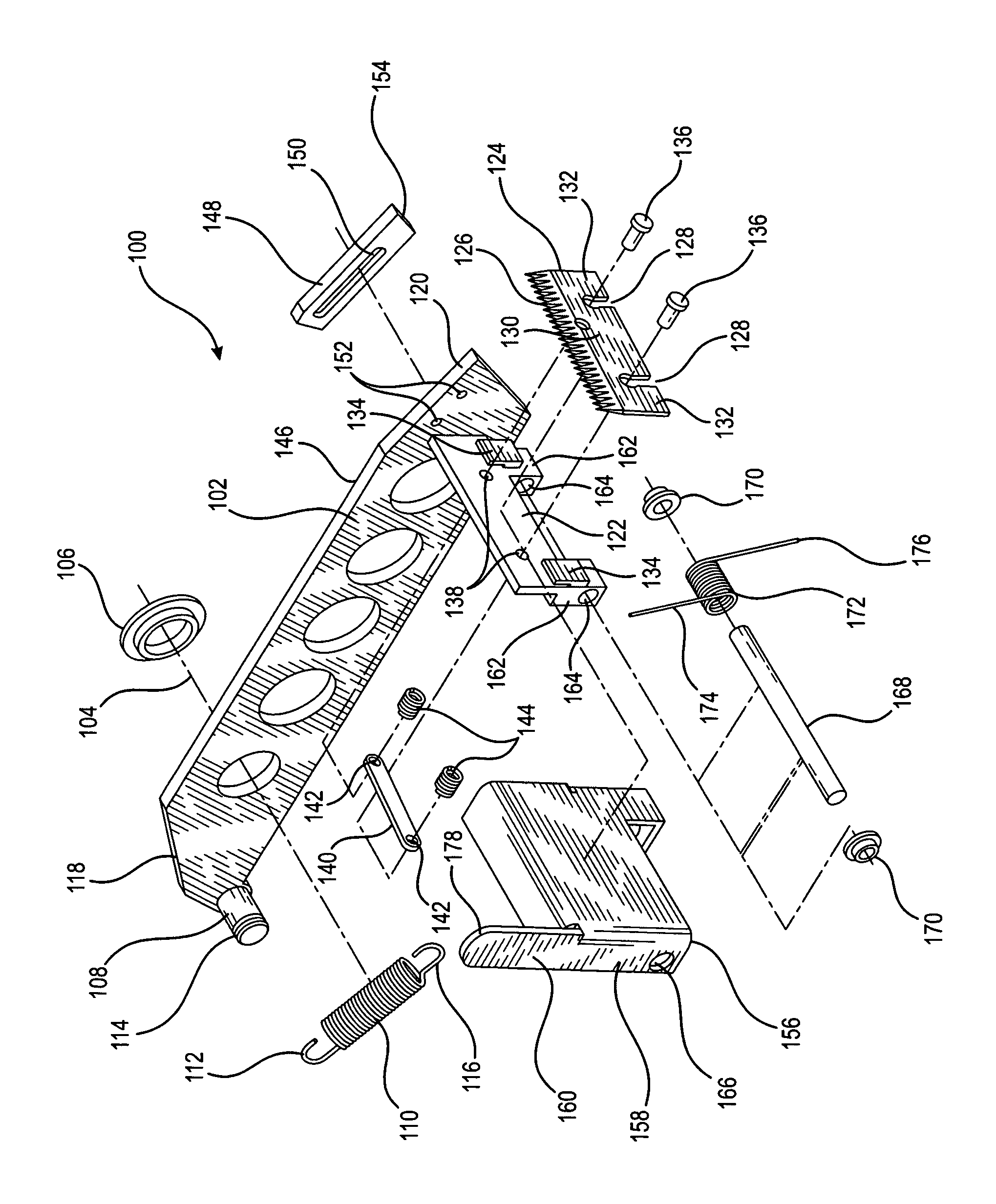
[0008]Referring now to the drawings, and more particularly to the SOLE FIGURE thereof, a new and improved quick change knife blade assembly, constructed in accordance with the principles and teachings of the present invention and showing the cooperative parts thereof for use in conjunction with a tape roll dispensing cartridge assembly of a carton or case sealing machine, is disclosed and is generally indicated by the reference character 100. More particularly, it is seen that the new and improved quick change knife blade assembly 100 comprises a knife blade support arm 102 which is adapted to be pivotally mounted upon the framework of a carton or case sealing machine around a transverse axis 104 defined by means of a bushing member 106. The rear end portion of the knife blade support arm 102 is provided a transversely extending stud member 108, and a coil spring member 110 is provided such that a first hooked end portion 112 of the coil spring member 110 is adapted to be engaged wi...


PUM

PropertyMeasurementUnit
biasing forceaaaaaaaaaa
depression forceaaaaaaaaaa
timeaaaaaaaaaa

Abstract

A quick change knife blade assembly, for use in conjunction with a tape roll dispensing cartridge assembly of a case sealing machine, comprises a knife blade mounted upon a knife blade mounting plate. A pin plate is fixedly connected to mounting pins passing through the knife blade, and springs are interposed between the pin plate and the mounting plate so as to normally bias the pin plate to a position at which the mounting pins prevent the removal of the knife blade from the mounting plate. When the pin plate is depressed against the biasing forces of the springs, the mounting pins are moved so as to permit the knife blade to be removed from the mounting plate.

Description

FIELD OF THE INVENTION[0001]The present invention relates generally to carton or case sealing machines, and more particularly to a new and improved quick change knife blade assembly for use in conjunction with a tape roll dispensing cartridge assembly of the carton or case sealing machine wherein the knife blade or cutting member can be quickly replaced or exchanged by means of operator personnel, in lieu of maintenance personnel, as a result of a simple manual manipulation of particular structural components of the knife blade assembly without the need for any special tools.BACKGROUND OF THE INVENTION[0002]During the operation of carton or case sealing machines, numerous cartons or cases will be sealed by means of one or more tape roll dispensing cartridge assemblies which not only dispense the carton or case sealing tapes and apply the same to the carton or case, but in addition, comprise knife blade assemblies for cutting or severing the sealing tape at predetermined times during...

Claims


Application Information

Patent Timeline
Patent Type & Authority Patents(United States)
IPC IPC(8): B32B38/00B32B38/04B26B1/00
CPCB65H35/008B65H2601/324Y10T156/1361Y10T156/1348Y10T156/12
Inventor FOX, BRYCE J.MENTA, WILLIAM J.
Owner SIGNODE IND GRP
Why Eureka
Try Eureka