
Apparatus and associated methodology for improving timing resolution in gamma ray detection

a technology of gamma ray detection and apparatus, applied in the direction of calibration apparatus, x/gamma/cosmic radiation measurement, instruments, etc., can solve the problems of measurable degradation of timing resolution, relative delays between pmt signals within the neighborhood, and relative delays between photons of approximately 140 ps, etc., to achieve the effect of improving timing resolution

Active Publication Date: 2011-12-20
TOSHIBA MEDICAL SYST CORP
View PDF2 Cites 6 Cited by
  • Summary
  • Abstract
  • Description
  • Claims
  • Application Information

AI Technical Summary

Benefits of technology

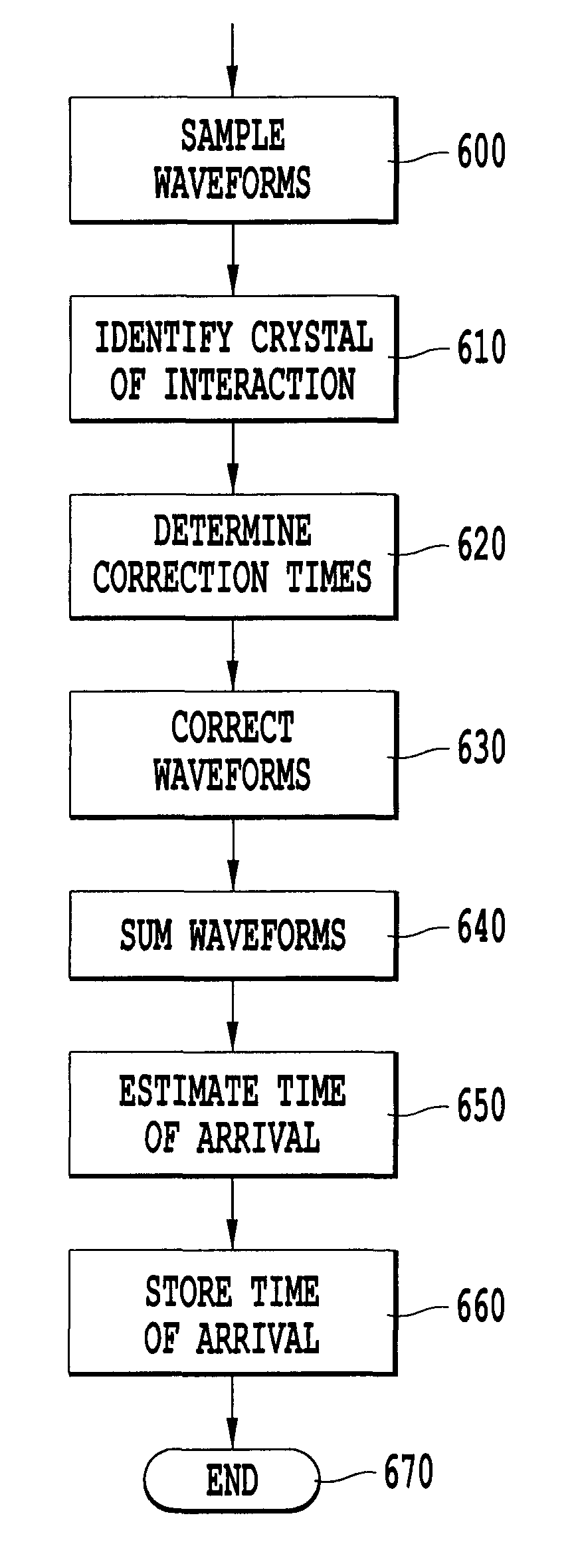
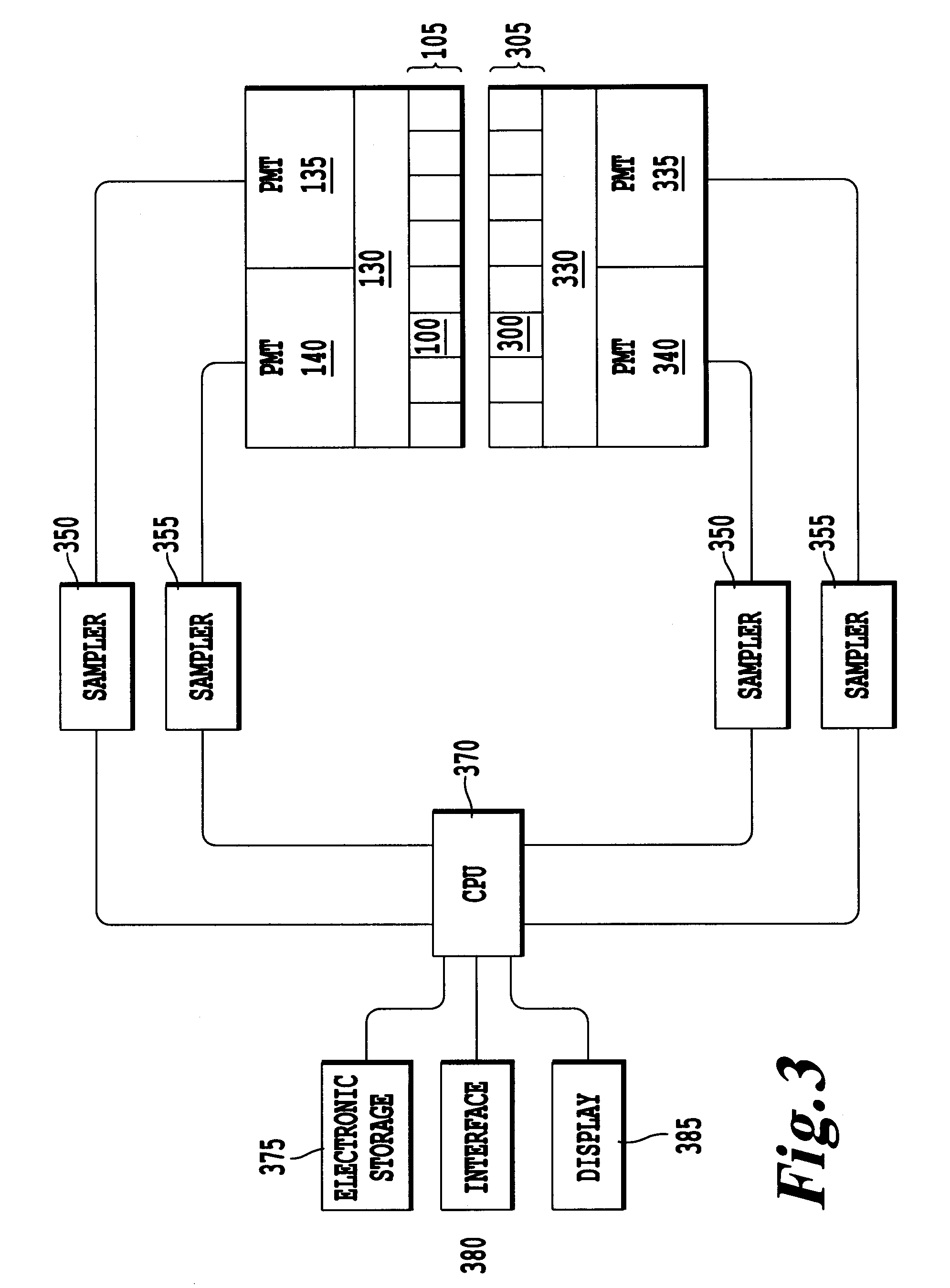
"The present invention provides a method for improving the timing resolution of a gamma ray detector by sampling waveforms from multiple photosensors over a crystal element. The method identifies the location of a scintillation event and determines correction times for each waveform based on the location. The waveforms are then corrected using the correction times and the time of arrival of the gamma ray is estimated based on the corrected waveforms. The invention also includes a gamma ray detector with a plurality of samplers and an electronic memory to store the waveforms after sampling. The data processor identifies the location of a scintillation event and determines correction times for each waveform. The invention provides a computer-readable medium with instructions for performing the method."

Problems solved by technology

Multiple effects can contribute to relative delays between the PMT signals within the neighborhood.
For example, a light guide with an index of refraction of 1.5 may cause a path length difference of 28 mm or more, leading to relative delays among the photon of approximately 140 ps within the light guide itself for photons traveling to two or more different PMTs.
These delays cause a measurable degradation in timing resolution for commercial positron emission tomography (PET) systems, which strive towards timing resolutions of 400 ps or better.
Moreover, these relative delays are dependent upon the location of a crystal with which the gamma ray interacts, causing each PMT to lead or lag other PMTs in its neighborhood depending on the position of the crystal with which the gamma ray interacts relative to the PMTs.
Timing resolution in these conventional systems degrades with increasing count rate because the tails of previous signals on part of the PMTs in a trigger zone interfere with timing detection of subsequent gamma ray-crystal interactions.

Method used


Image

  • Apparatus and associated methodology for improving timing resolution in gamma ray detection
  • Apparatus and associated methodology for improving timing resolution in gamma ray detection
  • Apparatus and associated methodology for improving timing resolution in gamma ray detection

Examples


Embodiment Construction

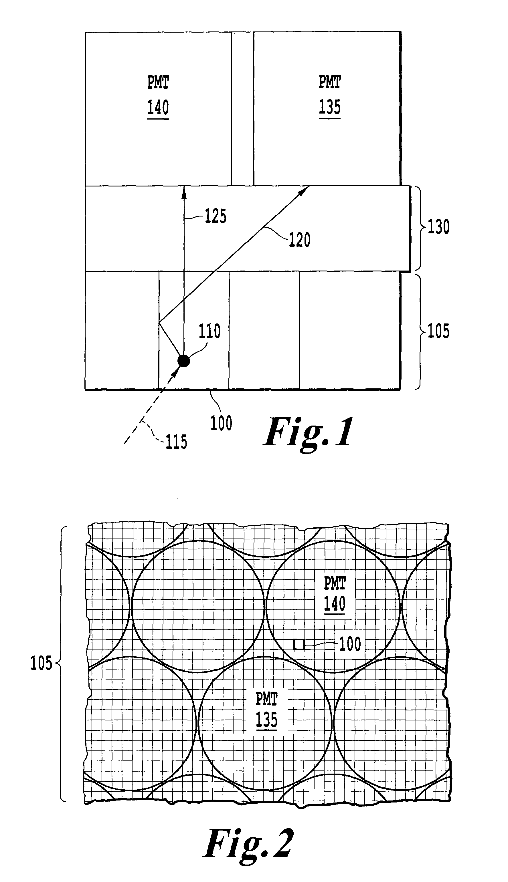
[0028]Referring now to the drawings, wherein like reference numerals designate identical or corresponding parts throughout the several views, FIG. 1 is a schematic drawing of gamma ray detection according to an exemplary embodiment of the present invention. In FIG. 1, a gamma ray detector includes photomultiplier tubes (PMT) 135 and 140 arranged over an array of scintillation crystals 105, with a light guide 130 therebetween. This discussion considers the case where PMTs are used as photosensors. However, one skilled in the art will recognize that any photosensors, including single-channel PMTs, multi-anode PMTs, avalanche photodiodes (APDs), arrays of APDs, silicon photomultipliers (SiPMs), or arrays of SiPMs can be used without departing from the scope of the present invention.

[0029]Further, one of ordinary skill in the art will recognize that though FIG. 1 includes an array of scintillation crystals, other gamma ray detection devices, such as monolithic scintillators, may be used...


PUM


Abstract

An apparatus and associated method for gamma ray detection that improves the timing resolution is provided. A crystal of interaction in a scintillation crystal array emits scintillation light in response to interaction with a gamma ray. The scintillation light is detected by one or more photomultiplier tubes. Each photomultiplier tube that detects the scintillation light detects the light at a different time. The apparatus determines the location of the gamma ray interaction and uses the location of the interaction to generate correction times for each waveform generated by the photomultiplier tubes. The waveforms are corrected with the correction timings and combined to extract a time of arrival estimate for the gamma ray. Noise thresholding is also used to select waveforms having low noise for combination to extract the time of arrival estimate.

Description

BACKGROUND OF THE INVENTION[0001]1. Field of the Invention[0002]The present disclosure generally relates to an apparatus and associated methodology for improving timing resolution in gamma ray detection. More specifically, the present disclosure relates to an apparatus and associated methodology for improving timing resolution in a gamma ray detection system, such as a positron emission tomography system, by generating timing corrections with respect to an identified interaction location.[0003]2. Discussion of the Background[0004]A commercial gamma ray detector includes an array of scintillator crystals coupled to a transparent light guide, which distributes scintillation light over an array of photomultiplier tubes (PMTs) arranged over the transparent light guide. A position of a gamma ray interaction within the array of scintillator crystals is generally encoded by spreading the optical signal corresponding to the gamma ray over several PMTs grouped into a neighborhood. By measuri...

Claims


Application Information

Patent Timeline
Patent Type & Authority Patents(United States)
IPC IPC(8): G01D18/00
CPCG01T1/208G01T1/1647
Inventor BURR, KENT C.GAGNON, DANIEL
Owner TOSHIBA MEDICAL SYST CORP
Learn More