Replica transistor voltage regulator

a transistor voltage regulator and replica technology, applied in the field of voltage regulators, can solve the problems of poor accuracy of conventional replica transistor voltage regulators, unsuitable for many circuits, and not wholly satisfactory, and achieve the effects of improving accuracy, improving power supply rejection ratio, and improving stability of feedback circuits

Active Publication Date: 2011-12-20
MONTEREY RES LLC
View PDF24 Cites 33 Cited by
  • Summary
  • Abstract
  • Description
  • Claims
  • Application Information

AI Technical Summary

Benefits of technology

[0009]The present invention provides a solution to these and other problems, and offers further advantages over conventional voltage regulators and methods of operating the same.
[0011]Preferably, the voltage regulator is a replica transistor voltage regulator comprising a replica leg including the replica source follower and the resistor network, and an output leg comprising the output source follower and further comprising a leaker transistor coupled between the source of the output source follower and circuit ground. More preferably, the leaker transistor comprises a drain coupled to the source of the output source follower and a source coupled to circuit ground. The leaker transistor is controlled by a DC bias voltage to leak current from the output-node to provide a constant minimum current flowing in the output source follower, thereby improving circuit stability and avoid floating nodes.
[0013]In another embodiment, the voltage regulator comprises a feedback circuit including a feedback transistor coupled between the source of the replica source follower and the output-node. The feedback transistor is controlled by a DC biasing voltage that can be varied to adjust a magnitude of the feedback voltage (Vfbk). In certain preferred embodiments, the feedback transistor is connected as a source follower having a source coupled to the source of the replica source follower and a drain coupled to the source of the output source follower. More preferably, the feedback transistor further comprises a bulk terminal coupled to the source thereof to improve the stability of the feedback circuit.
[0014]In another aspect the invention is directed to a method of operating a replica transistor voltage regulator to improve accuracy, while providing a good power supply rejection ratio (PSRR) and substantially no headroom limitations. In one embodiment, the method includes the step of coupling a feedback voltage (Vfbk) from the output-node to an inverting input of an OPAMP through a feedback resistor coupled between the output-node and a source of a replica source follower. In an alternative embodiment the feedback circuit comprises a feedback transistor coupled between the output-node and the source of the replica source follower, and the method includes the further step of controlling a biasing voltage to the feedback transistor to adjust a magnitude of Vfbk.

Problems solved by technology

Although the above described circuit is widely used, and has the advantages of a simple architecture that occupies a small area on a silicon die or substrate, it is not wholly satisfactory for a number of reasons.
In particular, conventional replica transistor voltage regulators suffer from poor accuracy, typically allowing the output voltage to vary by about 7-10% or more from a desired output voltage, making it unsuitable for use in many circuits.
Although voltage regulators including current conveyors provide regulation with a relatively good accuracy in output voltage, typically varying by as little as 5%, they too suffer from a number of drawbacks or disadvantages including poor headroom of less than about 50 millivolts (mV), and a poor power supply rejection ratio (PSRR), typically of about −5 decibels (dB) or greater.
More fundamentally, the current conveyor architecture requires a relatively large area on a die or substrate on which it is fabricated, utilizing from about 133K to 150K square microns (μm2), making it unsuitable for use in many integrated circuits (ICs).

Method used


Image

  • Replica transistor voltage regulator
  • Replica transistor voltage regulator
  • Replica transistor voltage regulator

Examples


Embodiment Construction

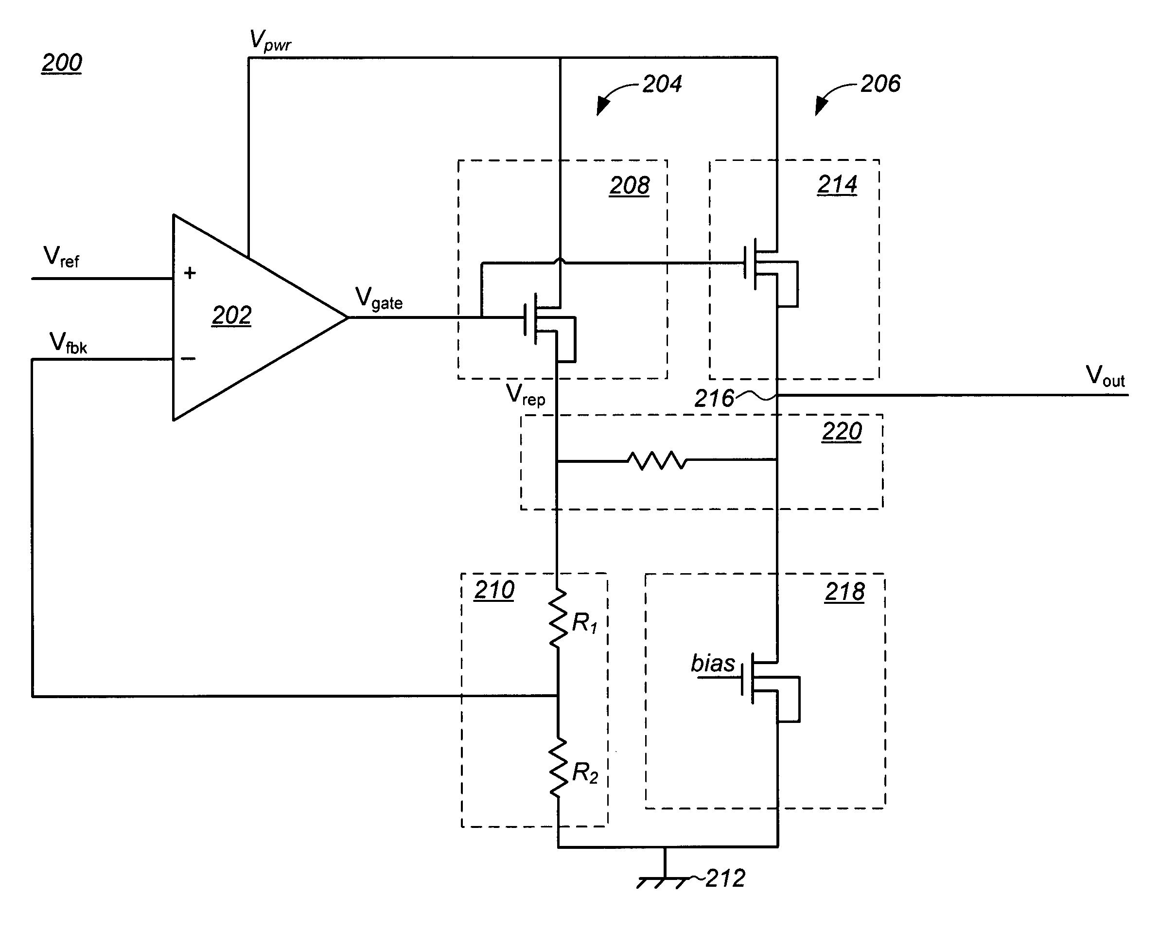
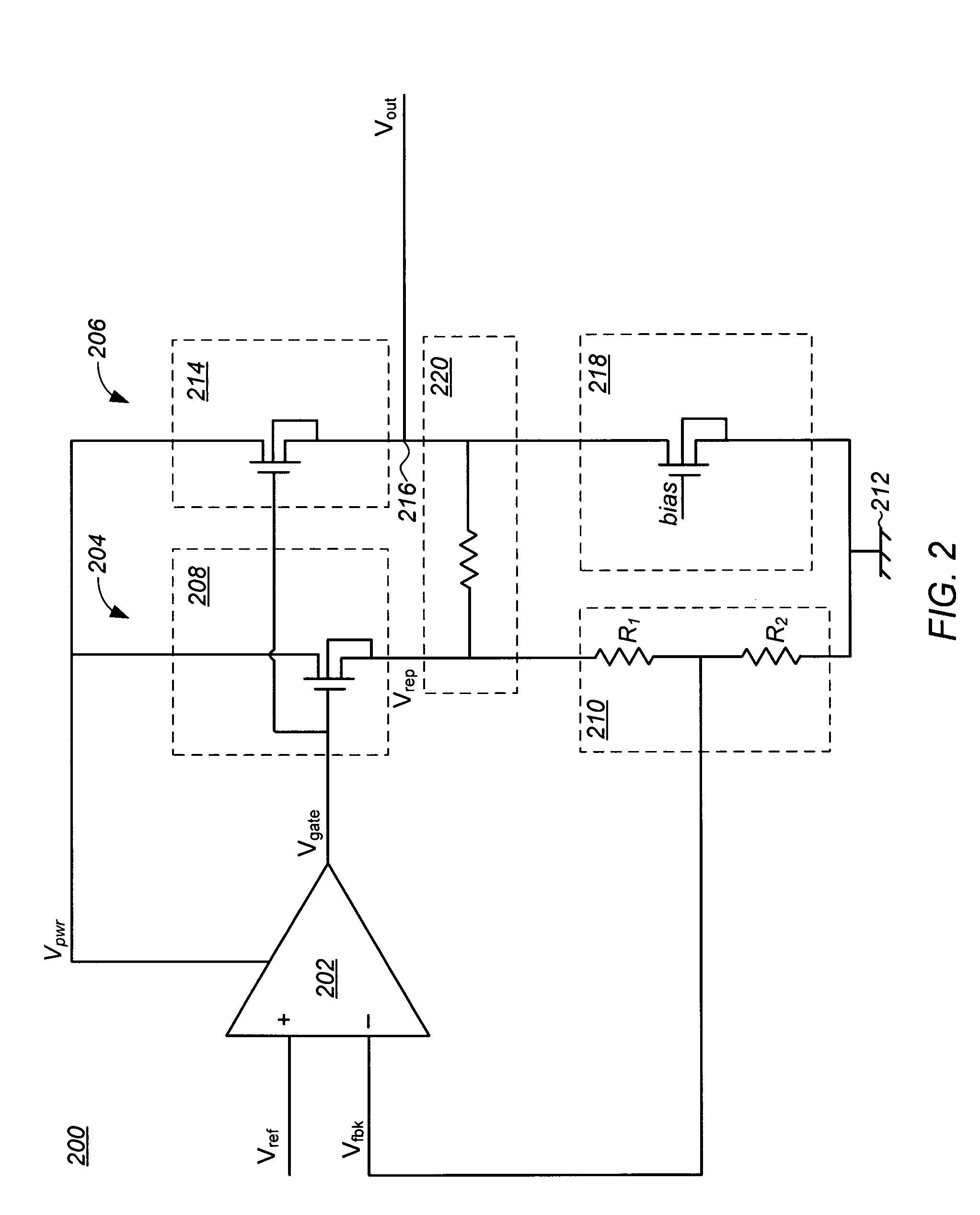
[0019]The present invention is directed to a replica transistor voltage regulator having a feedback loop between sources of an output source follower and a replica source follower.

[0020]The voltage regulator and method of the present invention are particularly useful in battery operated devices, such as a wireless computer mouse and other like devices, which include integrated voltage regulators fabricated on a common semiconductor die or substrate with integrated circuits (ICs) of the devices.

[0021]In the following description, for purposes of explanation, numerous specific details are set forth in order to provide a thorough understanding of the present invention. It will be evident, however, to one skilled in the art that the present invention may be practiced without these specific details. In other instances, well-known structures, and techniques are not shown in detail or are shown in block diagram form in order to avoid unnecessarily obscuring an understanding of this descrip...


PUM


Abstract

A voltage regulator is provided having high accuracy, low PSRR, and no headroom limitation. Generally, the regulator includes: an operational amplifier (OPAMP) having a non-inverting input coupled to a reference voltage; an output source follower coupled to and controlled by an output of the OPAMP, the output source follower including a drain coupled to a voltage source and a source coupled to an output-node of the regulator; a replica source follower coupled to and controlled by the OPAMP, the replica source follower including a drain coupled to the voltage source and a source coupled to circuit ground through a resistor network; and a feedback circuit extending from the output-node through a feedback resistor to the source of the replica source follower and through at least a first resistor of the resistor network to an inverting input of the OPAMP to couple a feedback voltage thereto. Other embodiments are also provided.

Description

CROSS-REFERENCE TO RELATED APPLICATIONS[0001]The present application claims the benefit of priority under 35 U.S.C. 119(e) to U.S. Provisional Patent Application Ser. No. 60 / 931,216 entitled “A Replica Transistor Voltage Regulator Architecture,” filed May 22, 2007, which application is hereby incorporated by reference in its entirety.TECHNICAL FIELD[0002]The present invention relates generally to voltage regulators, and more particularly to a circuit and method to substantially prevent or interrupt reverse current flow into a voltage regulator from an output thereof.BACKGROUND OF THE INVENTION[0003]Voltage regulator circuits or voltage regulators are widely used in many applications to provide a nearly constant output voltage at a desired level that is substantially independent of a poorly specified and often fluctuating input voltage and output conditions (i.e., variation in a load current).[0004]One type of voltage regulator is a replica transistor voltage regulator. In a replica ...

Claims


Application Information

Patent Timeline
Patent Type & Authority Patents(United States)
IPC IPC(8): G05F1/40G05F3/16
CPCG05F1/56
Inventor GEYNET, LIONEL
Owner MONTEREY RES LLC
Why Eureka
Try Eureka