Digital phase and frequency detector

Active Publication Date: 2011-12-20
AMLOGIC
View PDF7 Cites 11 Cited by
  • Summary
  • Abstract
  • Description
  • Claims
  • Application Information

AI Technical Summary

Benefits of technology

Yet another advantage of the present invention is that a digital phase and frequency detector is provided that can

Problems solved by technology

One disadvantage of the analog PLL structures is the silicon integration.
Another major disadvantage of conventional PLLs is lack of portability from one process technology to another.
Various approaches for digital phase and frequency detectors have been attempted but have draw backs, such as increased ha

Method used


Image

  • Digital phase and frequency detector
  • Digital phase and frequency detector
  • Digital phase and frequency detector

Examples


Example

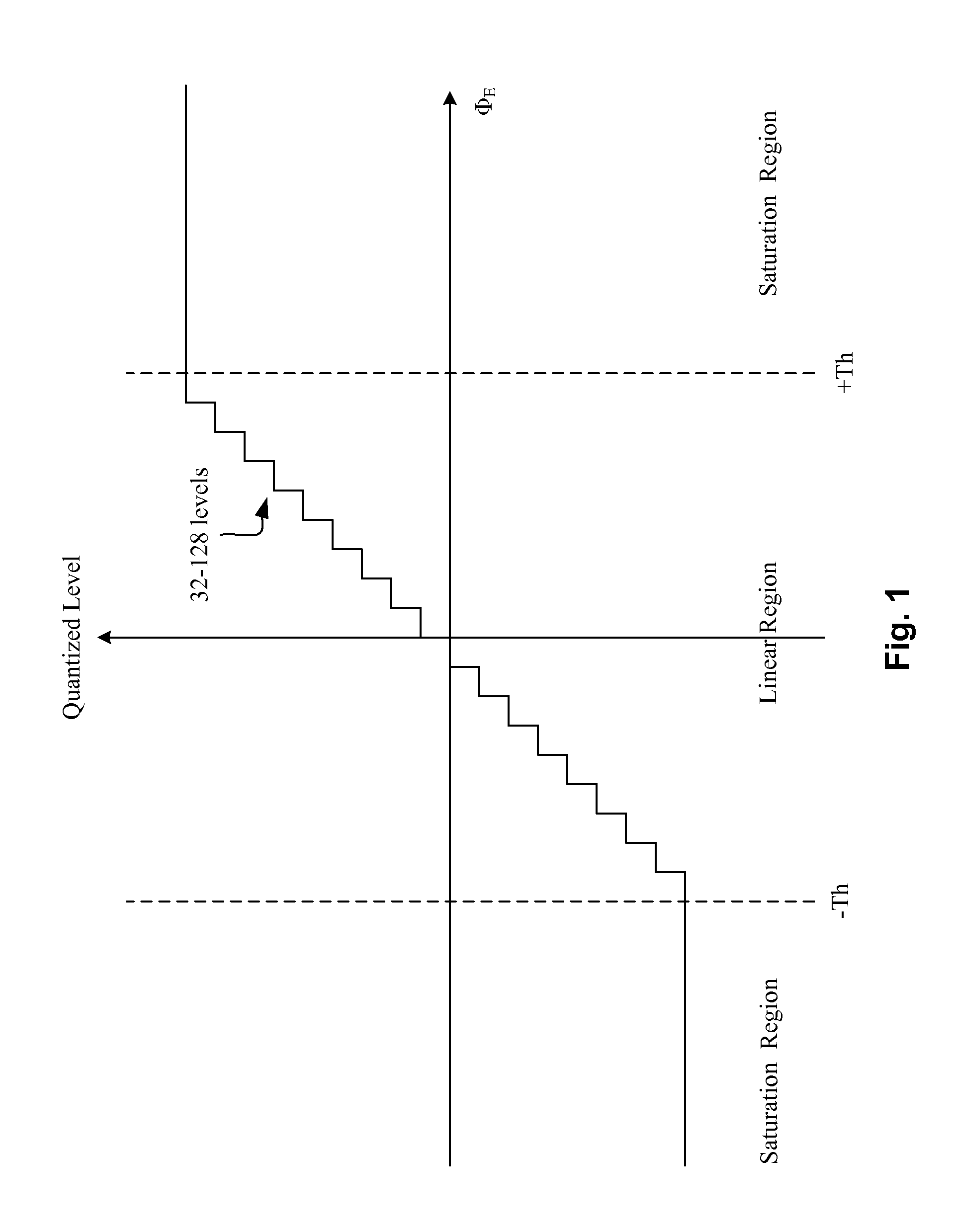
FIG. 1 illustrates a transfer curve for a digital phase and frequency detector of the present invention. A digital phase and frequency detector (“DPFD”) of the present invention can have at least two operating modes, including a linear operating mode and a saturation operating mode. In the linear operating mode, the DPFD outputs a quantized level to represent both the polarity and magnitude of the input phase error, ΦE, between a first input signal, e.g. a reference clock, and a second input signal, e.g. a feedback clock. In the saturation operating mode, the DPFD outputs a maximum constant level to represent the polarity of the input phase error between the first input signal and the second input signal. A transfer curve can be used to represent the quantized levels of the digital phase and frequency detector as a function of the input phase error of the two signals. Furthermore, the transfer curve can have a saturation region where the DPFD is in a saturation operating mode and a ...


PUM


Abstract

A method for digital phase detection, comprises the steps of: providing a reference clock; receiving a feedback clock; determining a timing difference between the reference clock and the feedback clock; determining a polarity that indicates the leading or lagging relationship between the reference clock and the feedback clock; adaptively selecting one of at least two operating modes for generating a quantized level indicative of the timing difference, wherein in a first operating mode the quantized level is a constant maximum value and wherein in a second operating mode the quantized level is proportional to the timing difference; and generating a digital phase detection output as a combination of the polarity and the quantized level.

Description

FIELD OF INVENTIONThis invention relates to a digital phase and frequency detector (“DPFD”), and, in particular, to a digital phase and frequency detector that can separately detect the polarity and magnitude of the phase difference of input signals and has at least two operating modes which can be adaptively switched.BACKGROUNDGenerally in electronics, a digital phase and frequency detector (“DPFD”) is a device which compares the phase and frequency of two input signals. The two inputs usually correspond to a voltage-controlled oscillator (“VCO”), as a feedback signal, and an external source as a reference signal. The DPFD can have two outputs for providing information to other circuitry for phase locking. To form a phase-locked loop (“PLL”), the DPFD's phase error output is fed to a loop filter which integrates the signal to smooth it. This smoothed signal is fed to a voltage-controlled oscillator which generates an output signal with a frequency that is proportional to the input ...

Claims


Application Information

Patent Timeline
IPC IPC(8): G01R25/00H03D13/00
CPCG01R25/08G01R23/15
Inventor ZHANG, WEICHENGSHI, MINGZOU, WEI-HUAYU, SHU-SUNCHAO, CHIEH-YUAN
Owner AMLOGIC
Why Eureka
Try Eureka