LADAR transmitting and receiving system and method

a technology of transmitting and receiving apparatus, applied in the direction of distance measurement, surveying and navigation, instruments, etc., can solve the problems of loss of alignment, difficulty in aligning, and high cost of arrangement, and achieve the effect of amplifying the photocurren

Active Publication Date: 2011-12-20
US SEC THE ARMY THE
View PDF10 Cites 167 Cited by
  • Summary
  • Abstract
  • Description
  • Claims
  • Application Information

AI Technical Summary

Problems solved by technology

However, non-metallic objects, such as rain and rocks produce weaker reflections, and some materials may produce no detectable reflection at all, meaning some objects or features are effectively invisible at radar frequencies.
This arrangement is generally expensive, very difficult to align, prone to losing alignment, subject to narcissus, and requiring much more space than desired for a compact LADAR system.
In addition, current compact LADAR systems have generally been flawed by one or more factors including, low pixelization, insufficient range or range resolution, image artifacts, no daylight operation, large size, high power consumption, and high cost.
Current LADAR systems frequently use a wide bandwidth photo detector / amplifier system with a small detector, and a low shunt capacitance, leading to an undesirable signal-to-noise ratio.

Method used


Image

  • LADAR transmitting and receiving system and method
  • LADAR transmitting and receiving system and method
  • LADAR transmitting and receiving system and method

Examples


Embodiment Construction

[0024]The embodiments herein and the various features and advantageous details thereof are explained more fully with reference to the non-limiting embodiments that are illustrated in the accompanying drawings and detailed in the following description. Descriptions of well-known components and processing techniques are omitted so as to not unnecessarily obscure the embodiments herein. The examples used herein are intended merely to facilitate an understanding of ways in which the embodiments herein may be practiced and to further enable those of skill in the art to practice the embodiments herein. Accordingly, the examples should not be construed as limiting the scope of the embodiments herein.

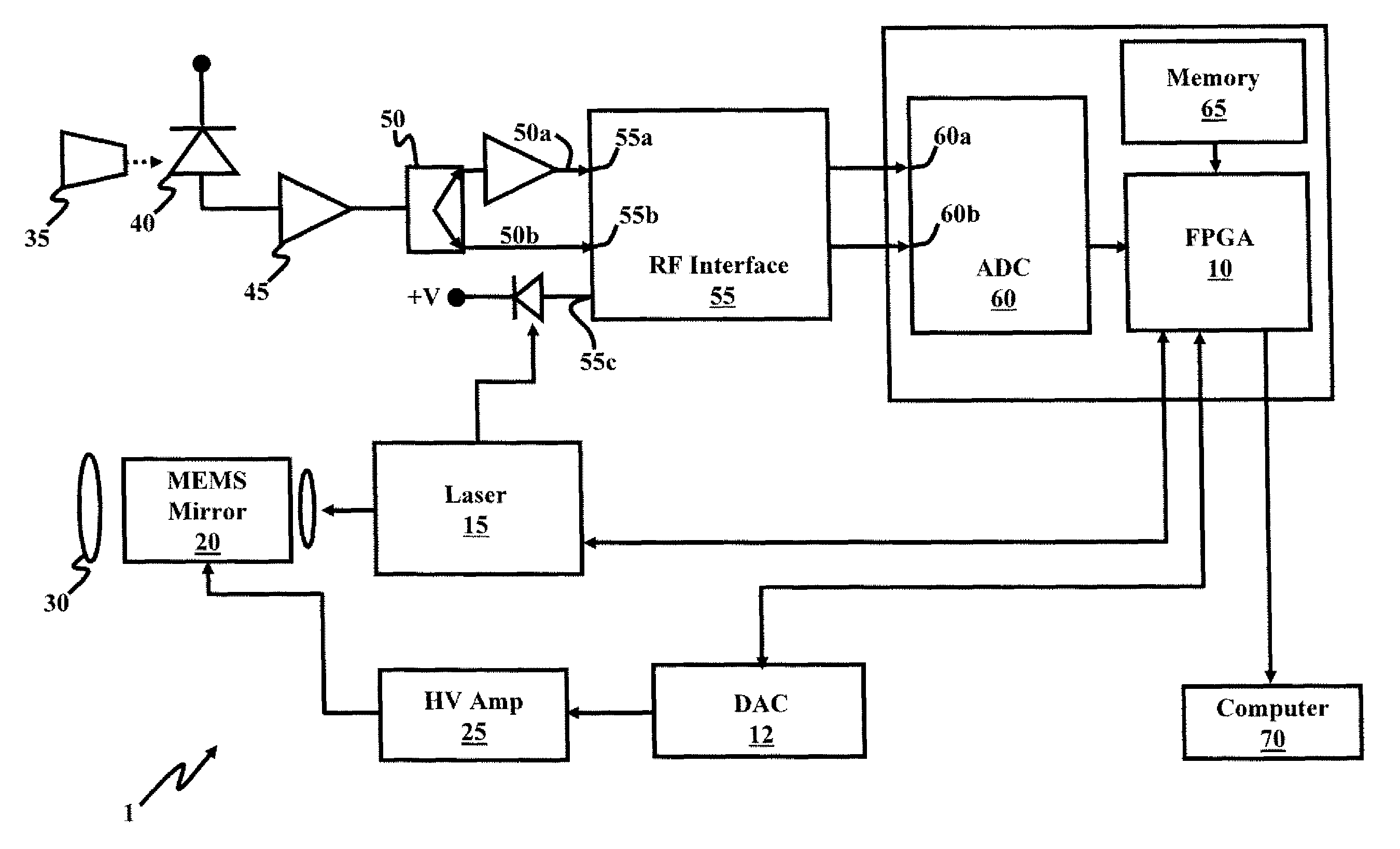
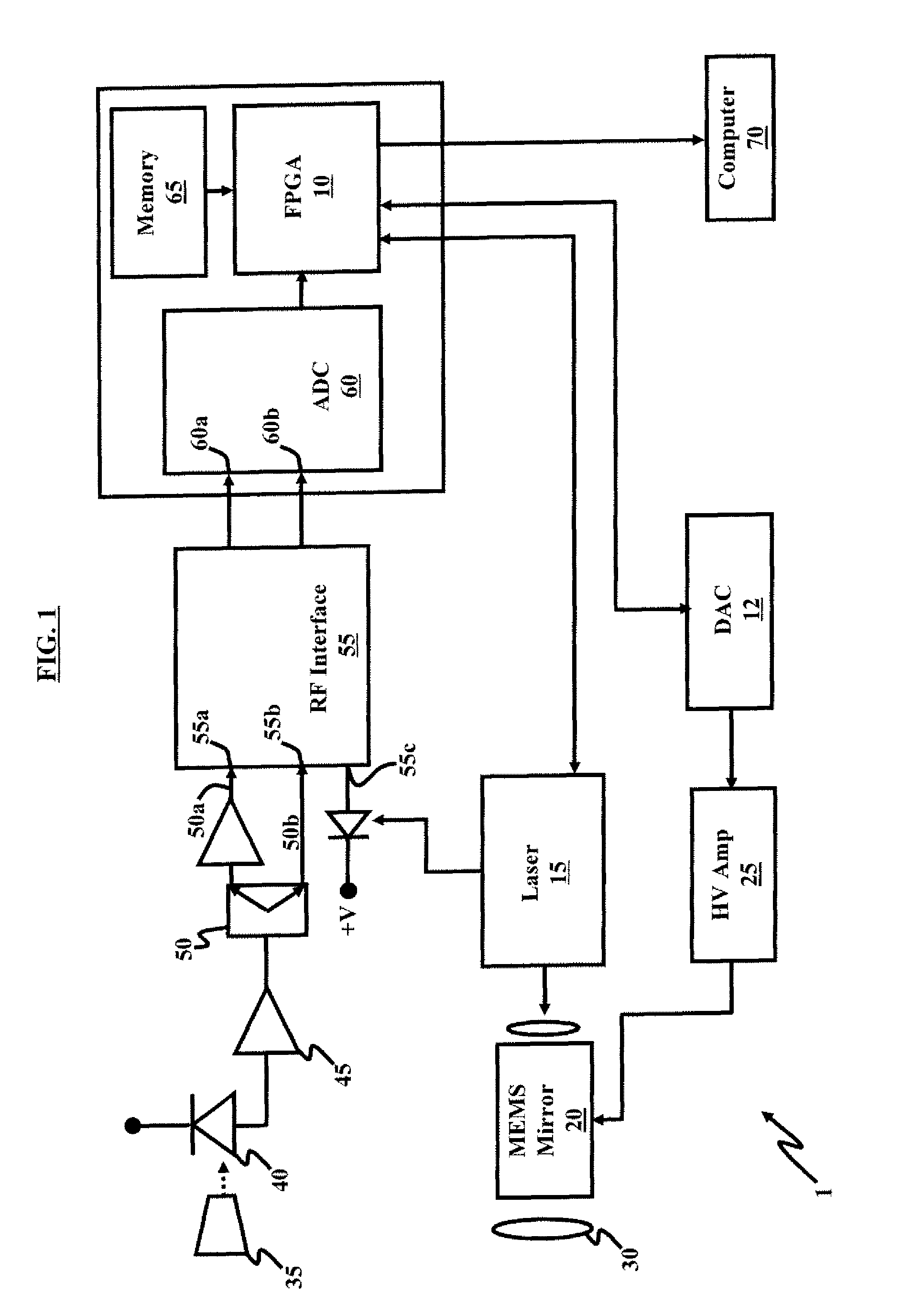
[0025]The embodiments herein provide a LADAR transmitting and receiving apparatus (or a LADAR transceiver), which facilitates the development of a compact, low-cost, and low-power LADAR imager for various applications, including small unmanned ground vehicles, and supports autonomous navigation...


PUM


Abstract

A compact LADAR transmitting and receiving apparatus includes a pulse laser generating pulses of light; a transmitter collimating and directing the pulses of light toward a target; a receiver collecting reflected pulses of light, the reflected pulses of light having been reflected from the target, the receiver comprising a tapered fiber bundle; a sensor operatively connected to the tapered fiber bundle, where the sensor comprises a photosensitive region and outputs a photocurrent; an amplifier amplifying the photocurrent; and a power divider splitting the amplified photocurrent between a high gain channel and a low gain channel; a RF interface accepting the high gain channel, the low gain channel, and an undelayed sample of a pulse of light generated from the pulse laser as input; a processing unit accepting output from the RF interface; and a display unit displaying output from the processing unit.

Description

GOVERNMENT INTEREST[0001]The embodiments herein may be manufactured, used, and / or licensed by or for the United States Government without the payment of royalties thereon.BACKGROUND[0002]1. Technical Field[0003]The embodiments herein generally relate to a LADAR transmitting and receiving apparatus, and, more particularly, to a compact LADAR transmitting and receiving apparatus provided at a reduced cost and with reduced power requirements.[0004]2. Description of the Related Art[0005]Laser Detection And Ranging (LADAR) is an optical remote sensing technology that measures properties of scattered light to find range and / or other information of a distant target. LADAR may be used in a variety of contexts for elastic backscatter light detection and ranging (LIDAR) systems. Although the acronym LADAR is usually associated with the detection of hard targets and the acronym LIDAR is usually associated with the detection of aerosol targets, there has been no real standard on their use and b...

Claims


Application Information

Patent Timeline
Patent Type & Authority Patents(United States)
IPC IPC(8): G01C3/08
CPCG01C3/08
Inventor STANN, BARRY LEEGIZA, MARK M.LAWLER, WILLIAM B.
Owner US SEC THE ARMY THE
Why Eureka
Try Eureka