

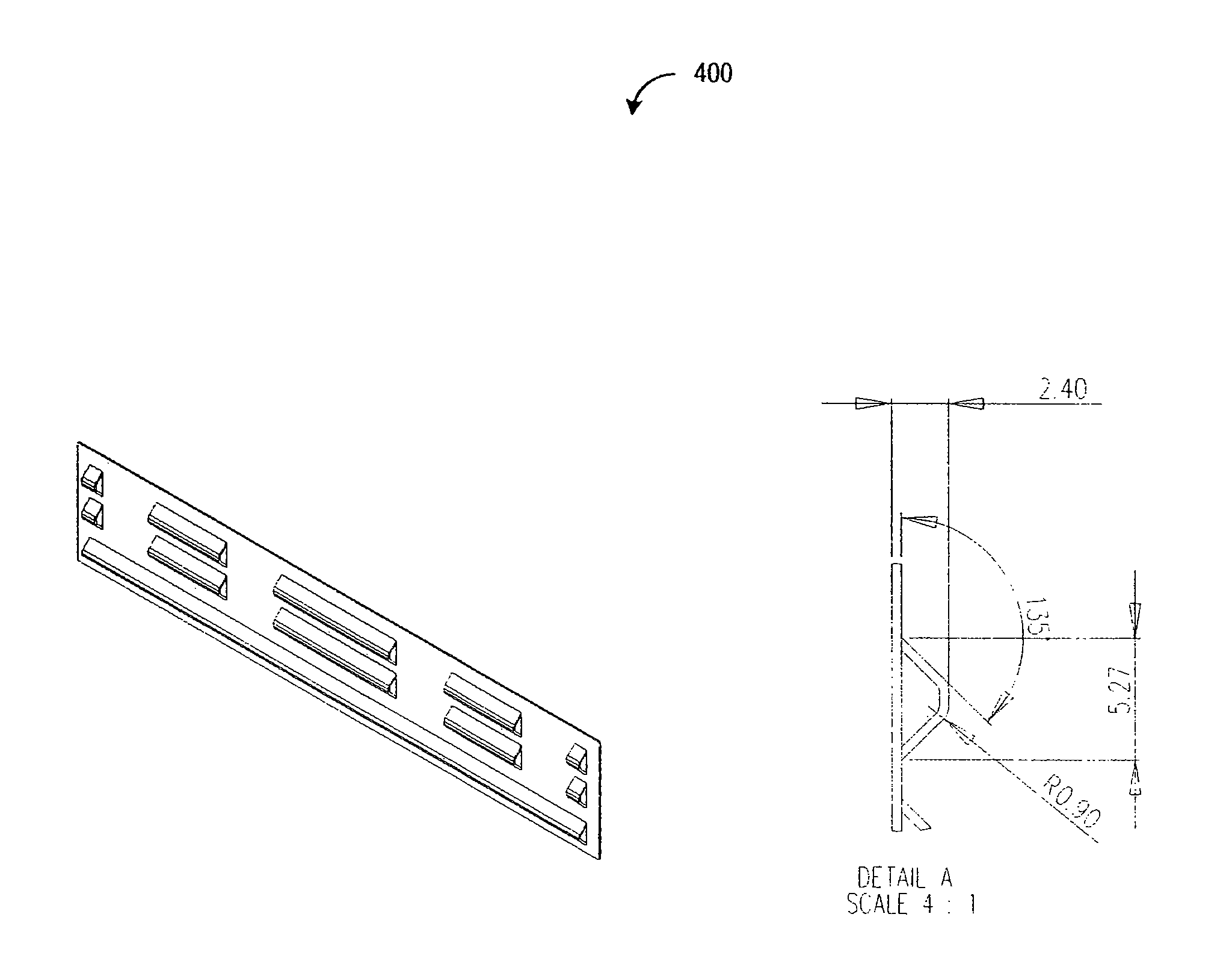
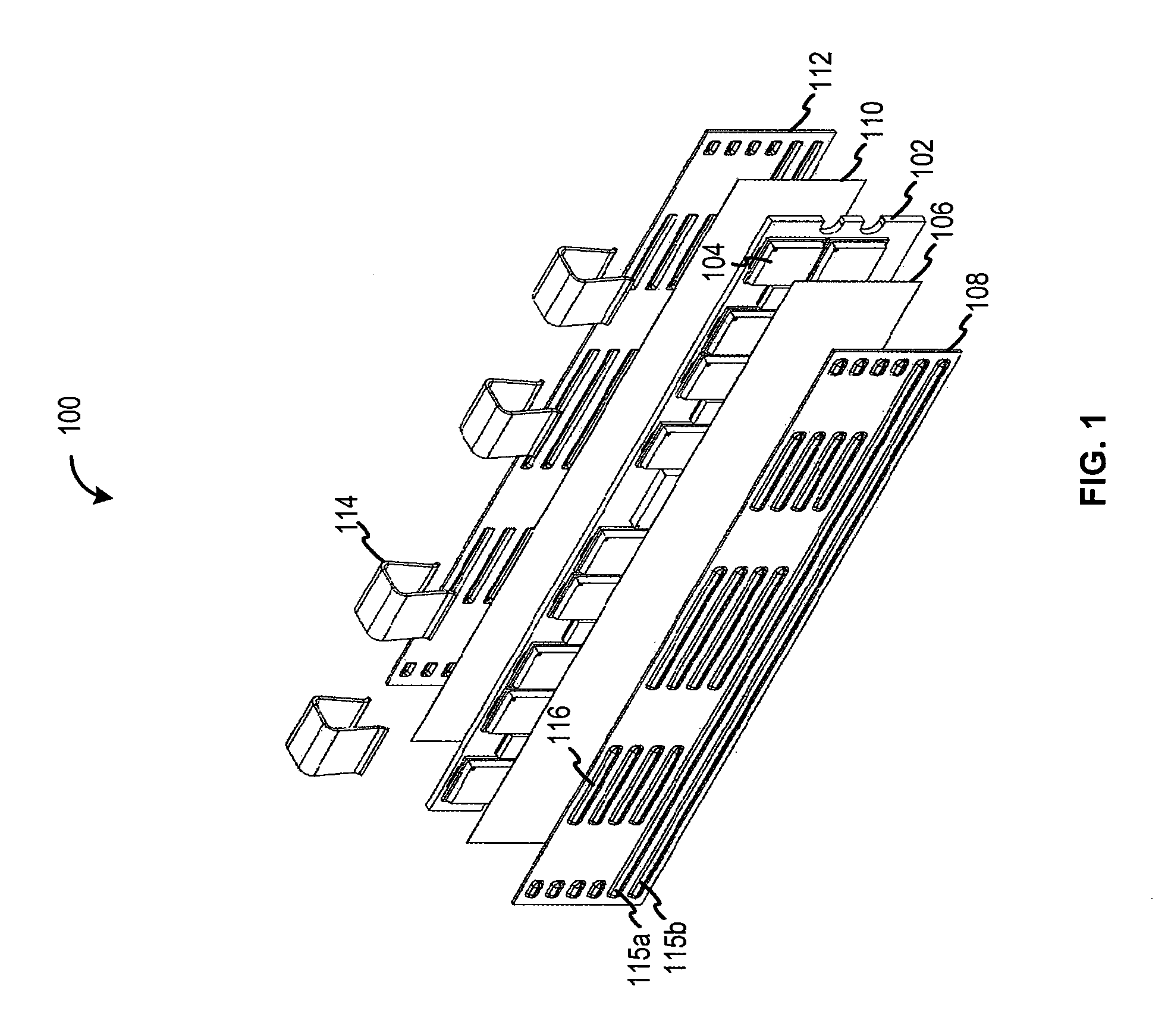
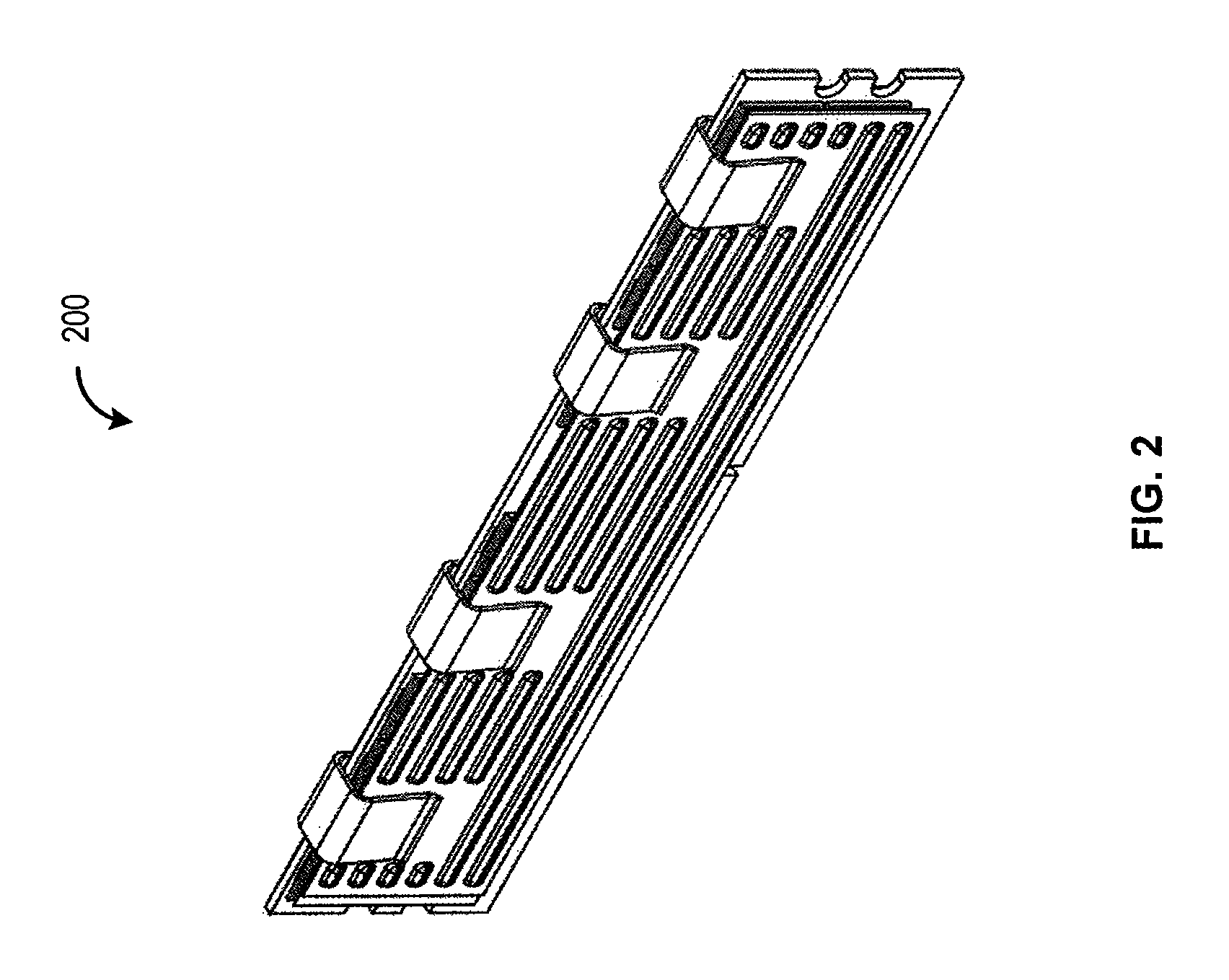
Embossed heat spreader
a heat spreader and heat dissipation technology, applied in the field of electronic systems, can solve the problems of increased memory power dissipation requirements, shortening the mechanical integrity of the module under shipping, handling, insertion/removal, etc., and achieves the effect of enhancing the rigidity of the heat spreader, and reducing the cost of heat dissipation
- Summary
- Abstract
- Description
- Claims
- Application Information
AI Technical Summary
Benefits of technology
Problems solved by technology
Method used
Image

Examples
Embodiment Construction
Embodiments of the present invention relate to design of a heat spreader (also commonly referred to as a “heat sink”) for memory modules. They may also be applied more generally to electronic sub-assemblies that are commonly referred to as add-in cards, daughtercards, daughterboards, or blades. These are sub-components that are attached to a larger system by a set of sockets or connectors and mechanical support components collectively referred to as a motherboard, backplane, or card cage. Note that many of these terms are sometimes hyphenated in common usage, i.e. daughter-card instead of daughtercard. The common characteristic linking these different terms is that the part of the system they describe is optional, i.e. may or may not be present in the system when it is operating, and when it is present it may be attached or “populated” in different locations which are functionally identical or nearly so but result in physically different configurations with consequent different flow...
PUM
 Abstract
Description
Claims
Application Information