Eureka AIR delivers breakthrough ideas for toughest innovation challenges, trusted by R&D personnel around the world.

Uniform-pressure shaping apparatus and system

a technology applied in the field of shapers and nozzles, can solve the problems of difficult to improve the yield rate of imprint products, difficult to press the whole template plane easily, and heat conduction may not be constant, so as to achieve the effect of low yield ra

Inactive Publication Date: 2011-12-27
CHENMING MOLD IND CORP
View PDF3 Cites 8 Cited by
  • Summary
  • Abstract
  • Description
  • Claims
  • Application Information

AI Technical Summary

Benefits of technology

[0007]In view of the shortcomings of the prior art, it is a primary objective of the invention to provide a uniform-pressure shaping apparatus, which overcomes the problem of low yield rate and also overcomes the non-uniform pressing and non-uniform heating problems of an object to be imprinted.
[0009]To achieve the foregoing objective, the present invention provides a uniform-pressure shaping system to overcome the problems of a non-uniform pressing and heating process of an object to be imprinted and a low yield rate.
[0016]In summation, the uniform-pressure shaping apparatus and system of the present invention have one or more of the following advantages:

Problems solved by technology

Compared with the shaft for transmitting pressure, the template has a plane of a large area, and the pressure of the template transmitted by the shaft is considered as a point pressure, so that the whole plane of the template may not be pressed easily.
As a result, the object to be imprinted is pressed by the template with a non-uniform pressure, and it is difficult to improve the yield rate of the imprint product, and only imprint products with a small size can be manufactured.
The heat conduction may have a non-constant speed due to factors such as the size of the imprint mold, the installation position of the heat pipe or water path, and the size of the object to be imprinted, and thus the object to be imprinted may be softened and non-uniform, and a low yield rate of the imprint product may result.

Method used


Image

  • Uniform-pressure shaping apparatus and system
  • Uniform-pressure shaping apparatus and system
  • Uniform-pressure shaping apparatus and system

Examples


Embodiment Construction

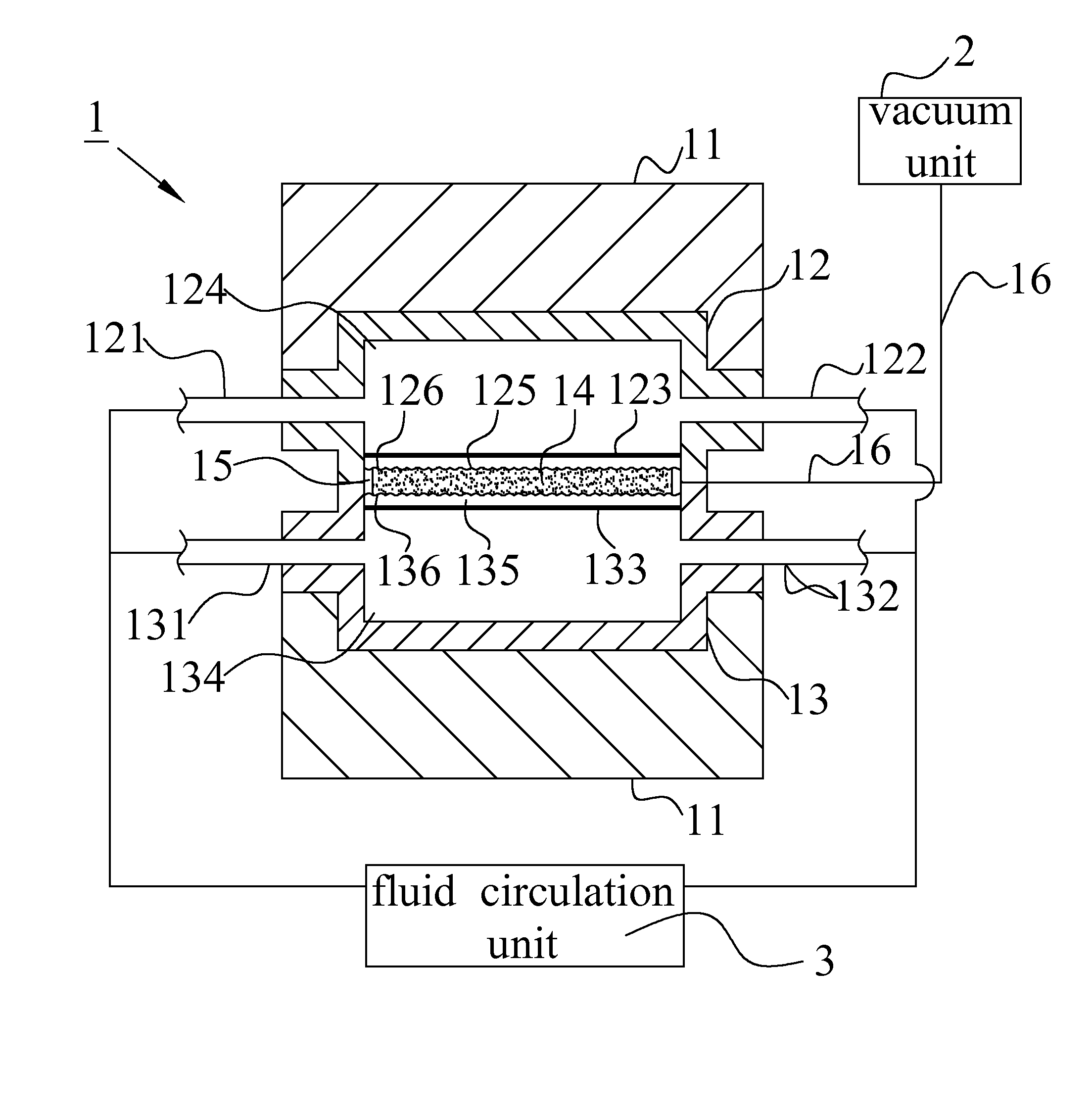
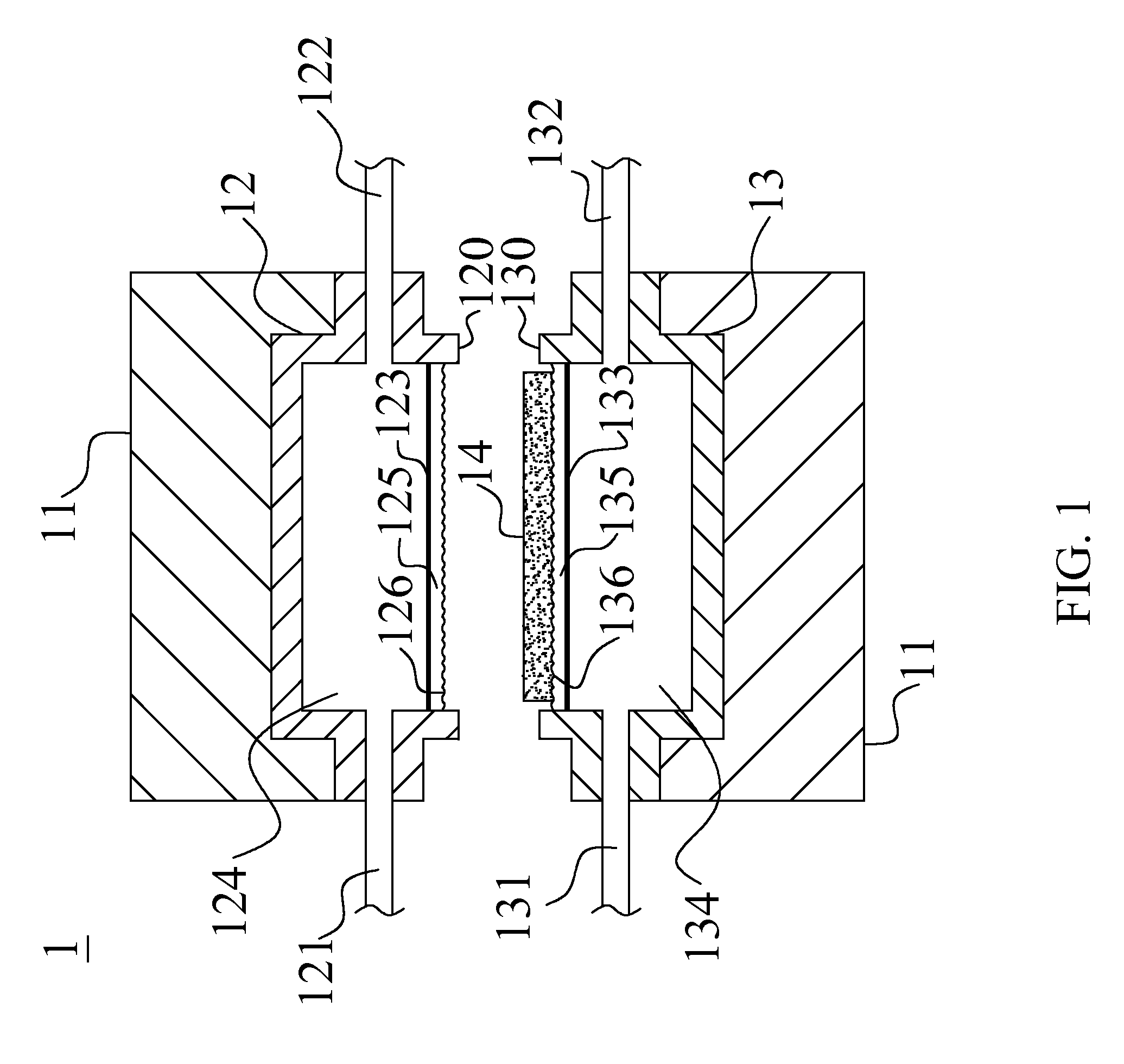
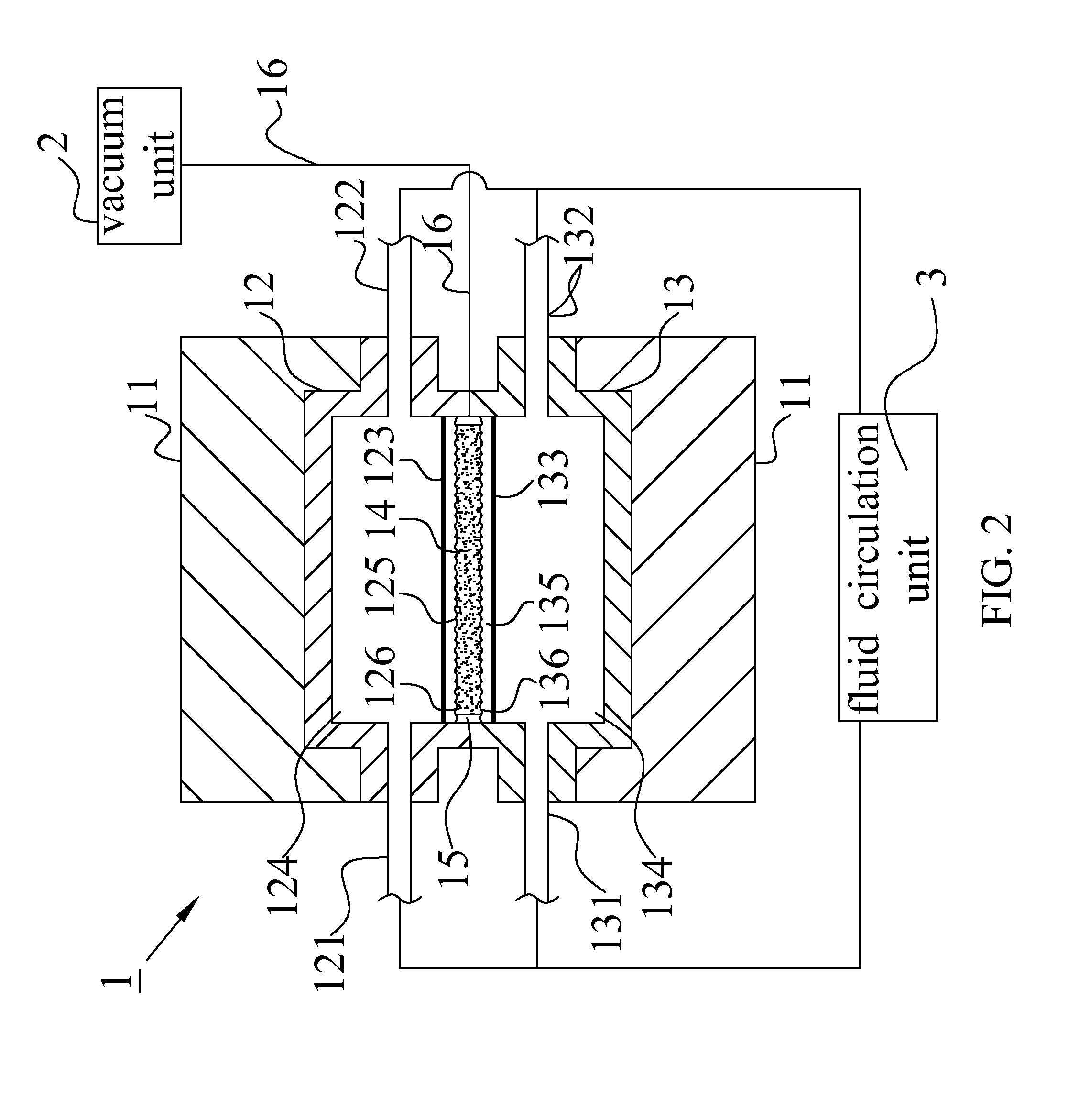
[0023]With reference to FIGS. 1 and 2 for a schematic view of a uniform-pressure shaping apparatus and a schematic view of opening and closing the uniform-pressure shaping apparatus in accordance with the present invention respectively, the uniform-pressure shaping apparatus comprises a first cavity 12 and a second cavity 13, wherein the first cavity 12 is disposed on a side of the molding machine 11, and the second cavity 13 is disposed on another side of the molding machine 11. The first cavity 12 is a cavity having a first open surface 120, and the first cavity 12 includes a first fluid inlet 121 and a first fluid outlet 122 formed at the periphery of the first cavity 12. The first heat conduction film 123 is installed at the first open surface 120 to seal the first cavity 12 to form a first sealed pressure chamber 124. A surface of the first template 125 is disposed on the first heat conduction film 123 with its backside aligning towards the first sealed pressure chamber 124, an...


PUM

PropertyMeasurementUnit
pressureaaaaaaaaaa
temperatureaaaaaaaaaa
sizeaaaaaaaaaa

Abstract

In a uniform-pressure shaping apparatus and system, the system comprises a uniform-pressure shaping apparatus, a vacuum unit and a fluid circulation unit, and the apparatus comprises a first cavity and a second cavity, each including a sealed pressure chamber, a heat conduction film and a template. An object to be imprinted is put on a pattern-imprinting surface of the template. When the first and second cavities get close to each other, the vacuum unit vacuums the space between the pattern-imprinting surfaces of the two templates. Meanwhile, the fluid circulation unit drives a hot fluid to pass through the two sealed pressure chambers. With the iso-pressure characteristic of the hot fluid, the object to be imprinted is heated and pressed uniformly until a desired shape is formed, and then a cold fluid is driven to pass through the two sealed pressure chambers to cool the object to be imprinted.

Description

BACKGROUND OF THE INVENTION[0001]1. Field of the Invention[0002]The present invention relates to a uniform-pressure shaping apparatus and system, and more particularly to a shaping apparatus and system using a fluid to apply pressure uniformly.[0003]2. Description of the Related Art[0004]In a conventional hot-press forming, an object to be imprinted is placed in a mold cavity of an imprint mold, and the imprint mold includes a set of upper and lower templates, and each of the upper and lower templates has an pattern-imprinting surface with an imprint pattern, and the object to be imprinted is placed between surfaces having the imprint patterns on the upper and lower templates, and then the imprint mold is closed. Now, the upper and lower templates will form a sealed mold cavity, and the object to be imprinted is situated in the sealed mold cavity. After the imprint mold is closed, the imprint mold is heated to soften the object to be imprinted to a plastic state, and then the imprin...

Claims


Application Information

Patent Timeline
Patent Type & Authority Patents(United States)
IPC IPC(8): B29C59/02
CPCB29C35/007B29C43/021B29C43/10B29C43/36B29C43/52B29C59/02B29C2043/025B29C2043/3238Y10S425/019
Inventor CHUANG, YUAN-LIKAO, MING-TZE
Owner CHENMING MOLD IND CORP
Why Eureka
Eureka Blog
Learn More