Torque limiter

a limiter and torque technology, applied in the direction of couplings, mechanical devices, slip couplings, etc., can solve the problems of excessive torque, damage to the bone, and “strip” threads in the bone,

Inactive Publication Date: 2011-12-27
RPH ENTERPRISES INC
View PDF16 Cites 28 Cited by
  • Summary
  • Abstract
  • Description
  • Claims
  • Application Information

AI Technical Summary

Benefits of technology

[0012]When torque is applied to the outer cylindrical housing, the roller bearings are forced against the elastic cylinder. At low torque levels, the elastic cylinder is sufficiently resilient such that, while the roller bearings may retract somewhat, they still remain in contact with the semicircular grooves. As such, the roller bearings couple the outer cylindrical housing to the inner cylindrical housing, allowing torque to be transferred therebetween. However, if the torque applied to the outer cylindrical housing exceeds a torque limit, the elastic cylinder will compress further and allow the roller bearings to fully retract into the inner cylindrical housing. When in this state, the semicircular grooves lose contact with the roller bearings and the outer cylindrical housing is decoupled from the inner cylindrical housing, and may rotate freely. This free rotation essentially prevents torque from being transmitted to the inner cylindrical housing, and thus any load attached thereto.
[0015]Further, by appropriately selecting the materials used to construct the torque limiter, the torque limiter may be implemented as a single-use disposable device, or as a reusable device. A disposable implementation may be constructed from materials that withstand ethylene oxide (ETO) and / or Gamma sterilization, but substantially deteriorate if exposed to high-temperature steam used in autoclaves. Such deterioration may discourage inadvertent, unpermitted or otherwise unwanted repeated use. Further, a reusable implementation may be constructed of materials that can withstand a variety of types of sterilization, including ETO, Gamma, and high temperature steam.

Problems solved by technology

Excessive torque may “strip” threads in the bone, or may otherwise damage the bone.
Further excessive torque may damage screws or other fasteners, for example by stripping the head of a fastener made from a delicate bioabsorbable material.
If excessive torque is applied, the plates simply begin to slip.
While existing torque limiters may be acceptable for certain applications, they are poorly suited for use in surgical procedures, such as installing screws or other fasteners into bone.
Many existing torque limiters are not resilient to certain sterilization techniques.
Thus, such torque limiters are often incompatible with autoclaves, which typically use high-temperature steam to sterilize surgical instruments.
Other designs may not be compatible with ethylene oxide (ETO) and / or Gamma sterilization.
Many existing torque limiters are also quite complicated.
Such complexity may lead to unacceptable size and weight characteristics, increased occurrence of failures and malfunctions, and high costs.
Indeed, many existing torque limiters are quite unsuited for single-use applications given their complexity and resultant cost.
Finally, many existing torque limiters are not as accurate and precise as desired at the low torque levels commonly used in surgical procedures.
Such deterioration may discourage inadvertent, unpermitted or otherwise unwanted repeated use.

Method used


Image

  • Torque limiter
  • Torque limiter
  • Torque limiter

Examples


Embodiment Construction

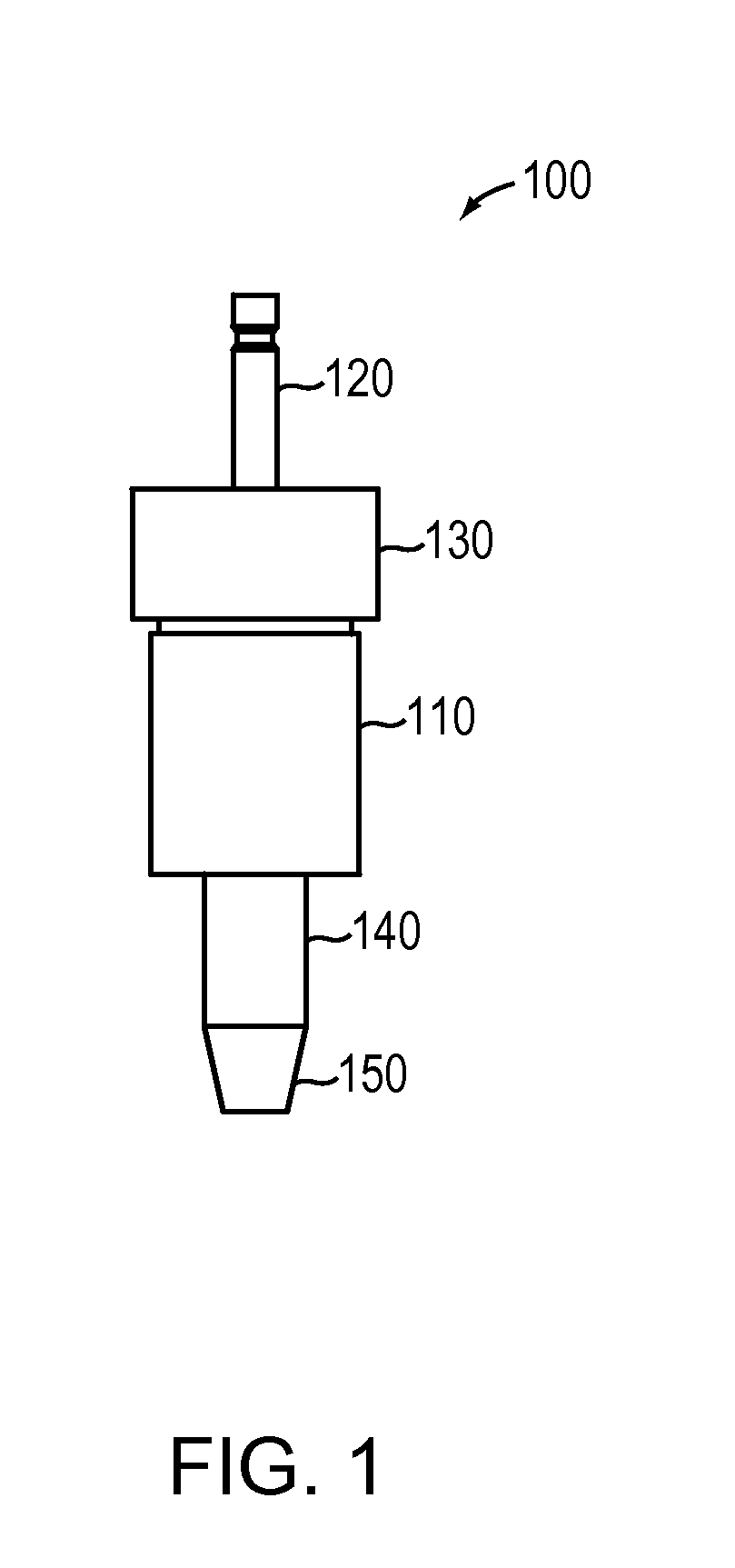
[0026]As shown in FIG. 1, an example torque limiter 100 according to an illustrative embodiment of the present disclosure includes an outer cylindrical housing 110 to which torque is applied via a shaft 120 affixed thereto by a coupling 130. The shaft 120 may be attached to a hand tool (not shown), for example to a ratcheting or non-ratcheting driver, or to a power tool (not shown), for example an electric or pneumatic drill, which is used to generate torque.

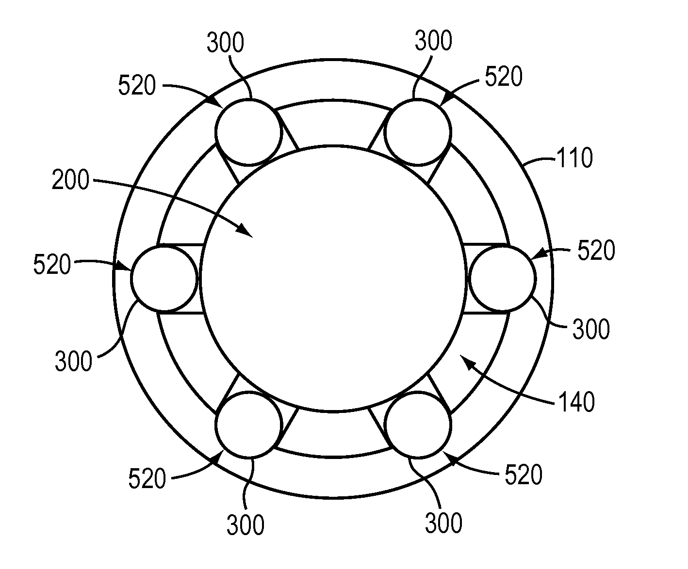
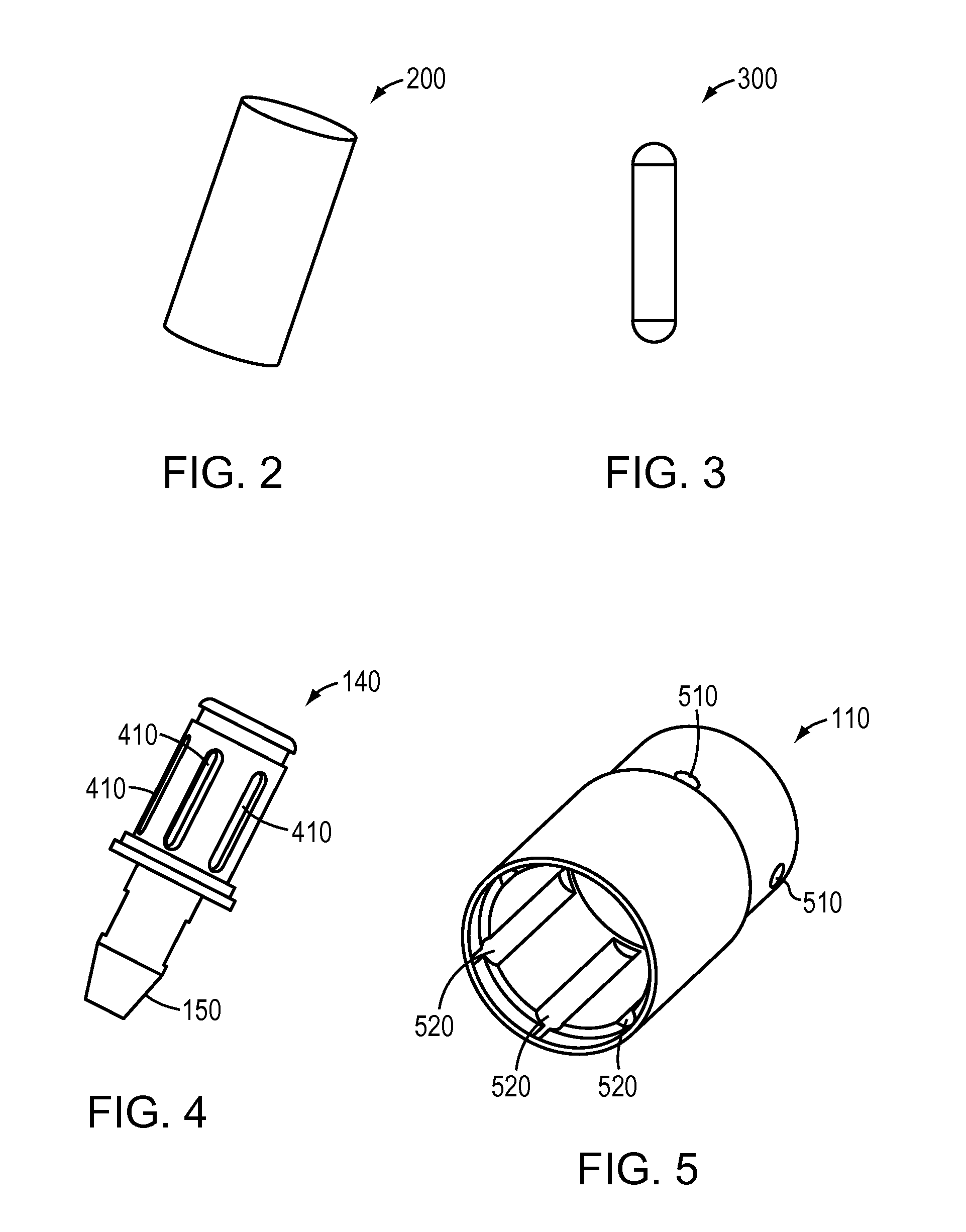
[0027]An inner cylindrical housing 140 (only partially visible in FIG. 1) is disposed within the outer cylindrical housing 110. The inner cylindrical housing 140 is affixed to an adaptor 150 which may be coupled to a bit (not shown) or other implement for delivering torque to a load, for example a screw or other fastener. The adaptor 150 may be a standard adaptor, for example, an AO pull adaptor, an AO push adaptor, a ¼ inch square adaptor, a small Zimmer adaptor, a Hudson adaptor, a standard Zimmer adaptor, ¼ inch square quick ...


PUM


Abstract

In one embodiment, a torque limiter comprises an outer cylindrical housing having a plurality of semicircular grooves disposed in an interior surface. An inner cylindrical housing is arranged at least partially within the outer cylindrical housing. The inner cylindrical housing has a plurality of slots passing from its interior surface to its exterior surface. A plurality of roller bearings are disposed within the slots. An elastic cylinder is also arranged within the interior of the inner cylindrical housing. When applied torque is below a torque limit, the elastic component presses the roller bearings into contact with the semicircular grooves to couple the outer and inner cylindrical housing. In response to applied torque exceeding the torque limit, the elastic component compresses sufficiently to allow the roller bearings to retract and disengage the semicircular grooves, thereby decoupling the outer and the inner cylindrical housings and preventing the transfer of torque.

Description

BACKGROUND[0001]1. Technical Field[0002]The present disclosure relates generally to torque limiters and more specifically to a torque limiter suitable for use in surgical procedures.[0003]2. Background Information[0004]It is increasingly common for a surgeon or other medical practitioner to insert fasteners into the human body to promote proper healing. For example, orthopedists often treat a variety of different types of bone fractures and other skeletal conditions by installing bone screws, rod and cap screws, or other fasteners in the affected area, to stabilize the bone, to secure implants, or for other therapeutic purposes. Bone screws or other fasteners may require predrilled and tapped holes, or may be self-drilling and self-tapping. When installing a screw or other fastener into bone, it is important that the bone not be subject to excessive torque. Excessive torque may “strip” threads in the bone, or may otherwise damage the bone. Further excessive torque may damage screws ...

Claims


Application Information

Patent Timeline
Patent Type & Authority Patents(United States)
IPC IPC(8): F16D9/02
CPCF16D7/10
Inventor SILVER, WILLIAM J.JOHNSTON, MERLE
Owner RPH ENTERPRISES INC
Why Eureka
Try Eureka