Cuttings vessels for recycling oil based mud and water

a drilling fluid and cuttings technology, applied in the field of drilling fluid recycling systems and methods at drilling locations, can solve the problems of complex environmental problems, high cost, pollution, etc., and achieve the effect of facilitating the flow of fluids

Inactive Publication Date: 2011-12-27
MI
View PDF20 Cites 28 Cited by
  • Summary
  • Abstract
  • Description
  • Claims
  • Application Information

AI Technical Summary

Benefits of technology

[0018]In one aspect, embodiments disclosed herein relate to a system for recycling a drilling fluid that includes a first cuttings storage vessel and a second cuttings storage vessel. The system further includes a module fluidly connected to the first and second cuttings storage vessels, the module having a valve configured to fluidly connect the first and second cuttings storage vessels. The module further includes a filter system configured to fluidly connect to at least the second cuttings storage vessel, and at least one pump to facilitate the flow of a fluid between the first and second cuttings storage vessels.
[0019]In another aspect, embodiments disclosed herein relate to a module for use at a drilling location that includes a valve for directing drilling fluid between at least a first cuttings storage vessel disposed outside the module and a second cuttings storage vessel disposed outside the module. The module further includes a filter system for filtering the drilling fluid and at least one pump for facilitating the flow of the fluid between at least the first and second cuttings storage vessels.

Problems solved by technology

When the drilling mud reaches the platform, it is contaminated with small pieces of shale and rock that are known in the industry as well cuttings or drill cuttings.
The disposal of the drill cuttings and drilling mud is a complex environmental problem.
Drill cuttings contain not only the residual drilling mud product that would contaminate the surrounding environment, but may also contain oil and other waste that is particularly hazardous to the environment, especially when drilling in a marine environment.
In such a marine environment, the water is typically filled with marine life that cannot tolerate the disposal of drill cuttings waste.
Adding water creates additional problems of added volume and bulk, pollution, and transport problems.
Installing conveyors requires major modification to the rig area and involves extensive installation hours and very high cost.
This is a difficult and dangerous operation that may be laborious and expensive.
Space on offshore platforms is limited.
These lifting operations, as mentioned above, are difficult, dangerous, and expensive.
Additionally, many of these modularized operations include redundant equipment, such as pumps, valves, and tanks or storage vessels.
While theses systems and methods provide improved processes in recycling drilling fluid, they require the difficult, dangerous, and expensive lifting and installation operations, as described above.

Method used


Image

  • Cuttings vessels for recycling oil based mud and water
  • Cuttings vessels for recycling oil based mud and water
  • Cuttings vessels for recycling oil based mud and water

Examples


Embodiment Construction

[0025]In one aspect, embodiments disclosed herein relate to systems and methods for recycling drilling fluids at a drilling location. The drilling location may include both onshore and offshore drill sites. Additionally, embodiments disclosed herein relate to systems and methods for recycling drilling fluids using a module-based drilling fluid recovery system. More specifically, such embodiments relate to methods of using a module-based drilling fluid recovery system to convert cuttings storage and transfer vessels into components of the drilling fluid recovery system.

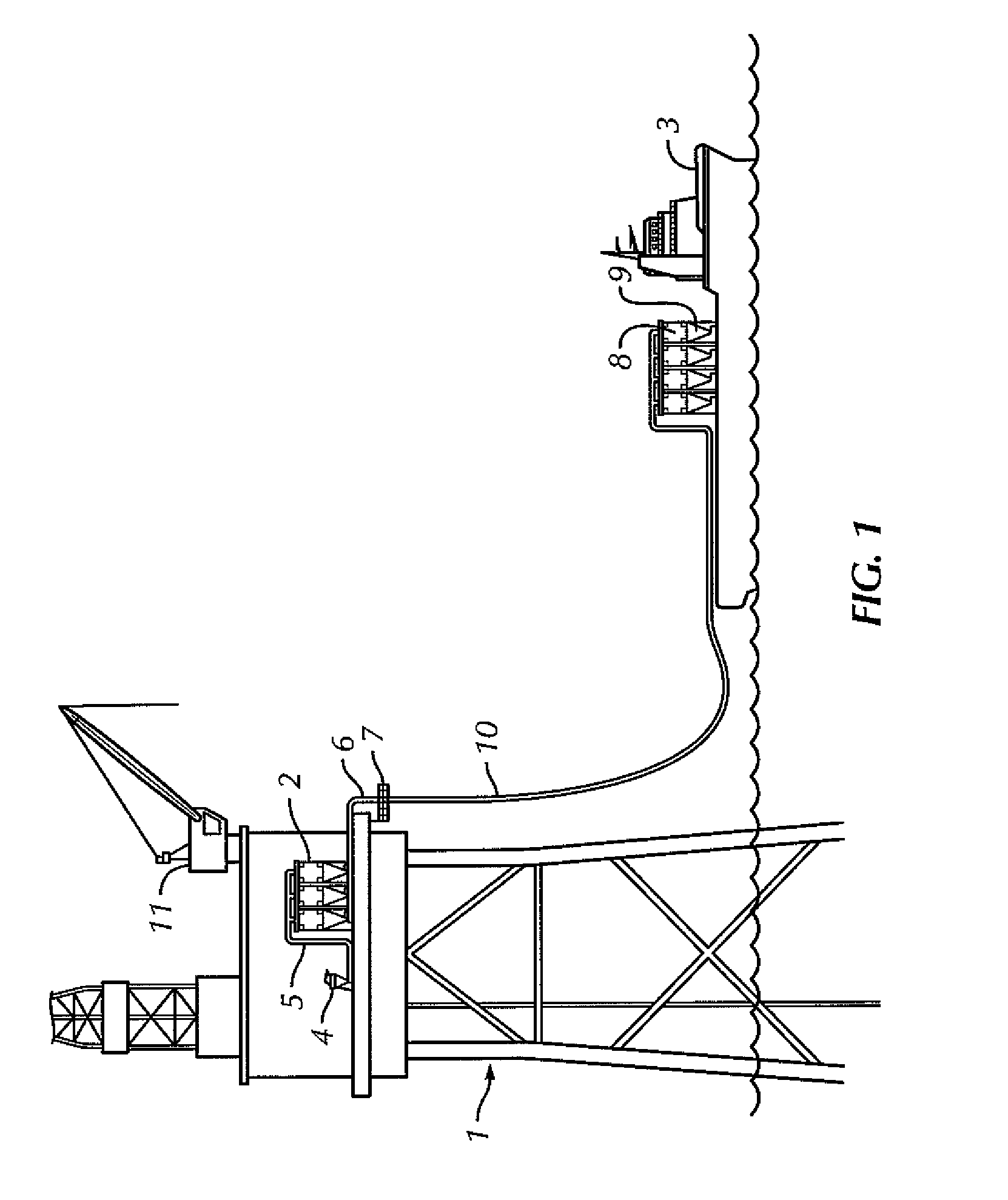
[0026]Referring initially to FIG. 1, a method of offloading drill cuttings from an offshore drilling rig according to one embodiment of the present disclosure is shown. In this embodiment, an offshore rig 1 may have one or more cuttings storage vessels 2 located on its platform. Cuttings storage vessels 2 may include raw material storage tanks, waste storage tanks, or any other vessels commonly used in association with...


PUM

PropertyMeasurementUnit
densityaaaaaaaaaa
chemicalaaaaaaaaaa
chemical dosingaaaaaaaaaa

Abstract

A system for recycling a drilling fluid that includes a first cuttings storage vessel, a second cuttings storage vessel, and a module fluidly connected to the first and second cuttings storage vessels, the module having a valve configured to fluidly connect the first and second cuttings storage vessels. The module further includes a filter system configured to fluidly connect to at least the second cuttings storage vessel, and at least one pump to facilitate the flow of a fluid between the first and second cuttings storage vessels. Also, a module for use at a drilling location that includes a valve for directing drilling fluid between at least a first cuttings storage vessel disposed outside the module and a second cuttings storage vessel disposed outside the module. The module further includes a filter system for filtering the drilling fluid and at least one pump for facilitating the flow of the fluid between at least the first and second cuttings storage vessels.

Description

CROSS-REFERENCE TO RELATED APPLICATION[0001]This application, pursuant to 35 U.S.C. §119(e), claims priority to U.S. Provisional Application Ser. No. 60 / 887,444, filed Jan. 31, 2007. That application is incorporated by reference in its entirety.BACKGROUND[0002]1. Field of the Disclosure[0003]Embodiments disclosed herein relate generally to systems and methods for recycling drilling fluids at a drilling location. More specifically, embodiments disclosed herein relate to systems and methods for recycling drilling fluids at a drilling location using a module-based drilling fluid recovery system. More specifically still, embodiments disclosed herein relate to systems and methods for recycling drilling fluids at a drilling location using a module to convert cutting storage and transfer vessels into a drilling fluid recovery system.[0004]2. Background[0005]In the drilling of wells, a drill bit is used to dig many thousands of feet into the earth's crust. Oil rigs typically employ a derric...

Claims


Application Information

Patent Timeline
Patent Type & Authority Patents(United States)
IPC IPC(8): B01D21/01B01D17/05
CPCE21B21/066
Inventor EIA, JAN THORE
Owner MI
Why Eureka
Try Eureka