Gravity separator, and a method for separating a mixture containing water, oil, and gas

a gravity separator and mixture technology, applied in the direction of liquid degasification, separation process, liquid displacement, etc., can solve the problems of high maintenance cost, high cost, and loss of capacity of prior art designs, so as to improve the separation process, improve the formation of gas phase and the effect of separation

Inactive Publication Date: 2012-01-03
SHCLUMBERGER NORGE AS
View PDF17 Cites 9 Cited by
  • Summary
  • Abstract
  • Description
  • Claims
  • Application Information

AI Technical Summary

Benefits of technology

[0019]Although the pressure in the vessel may vary and be within a wide range during operation from about 0.1 atm and upwards, it is normally preferred that the pressure in the vessel is in the range of 0.5 to 200 atm, conveniently in the range 1.0-100 atm. Adjustment of the pressure to an optimal value may improve formation of the gas phase and separation of the gas from the water and the oil.
[0020]To further improve the separation process the mixture containing water, oil, and gas is, in one embodiment, subjected to injection with one or more separation aids. Such separat

Problems solved by technology

The use of coalescer riser tubes with filters or of matrix plates complicates the separator and involves the risk

Method used


Image

  • Gravity separator, and a method for separating a mixture containing water, oil, and gas
  • Gravity separator, and a method for separating a mixture containing water, oil, and gas
  • Gravity separator, and a method for separating a mixture containing water, oil, and gas

Examples


Embodiment Construction

[0026]Further scope of applicability of the present invention will become apparent from the detailed description given hereinafter. However, it should be understood that the detailed description and specific examples, while indicating preferred embodiments of the invention, are given by way of illustration only, since various changes and modifications within the spirit and scope of the invention will become apparent to those skilled in the art from this detailed description.

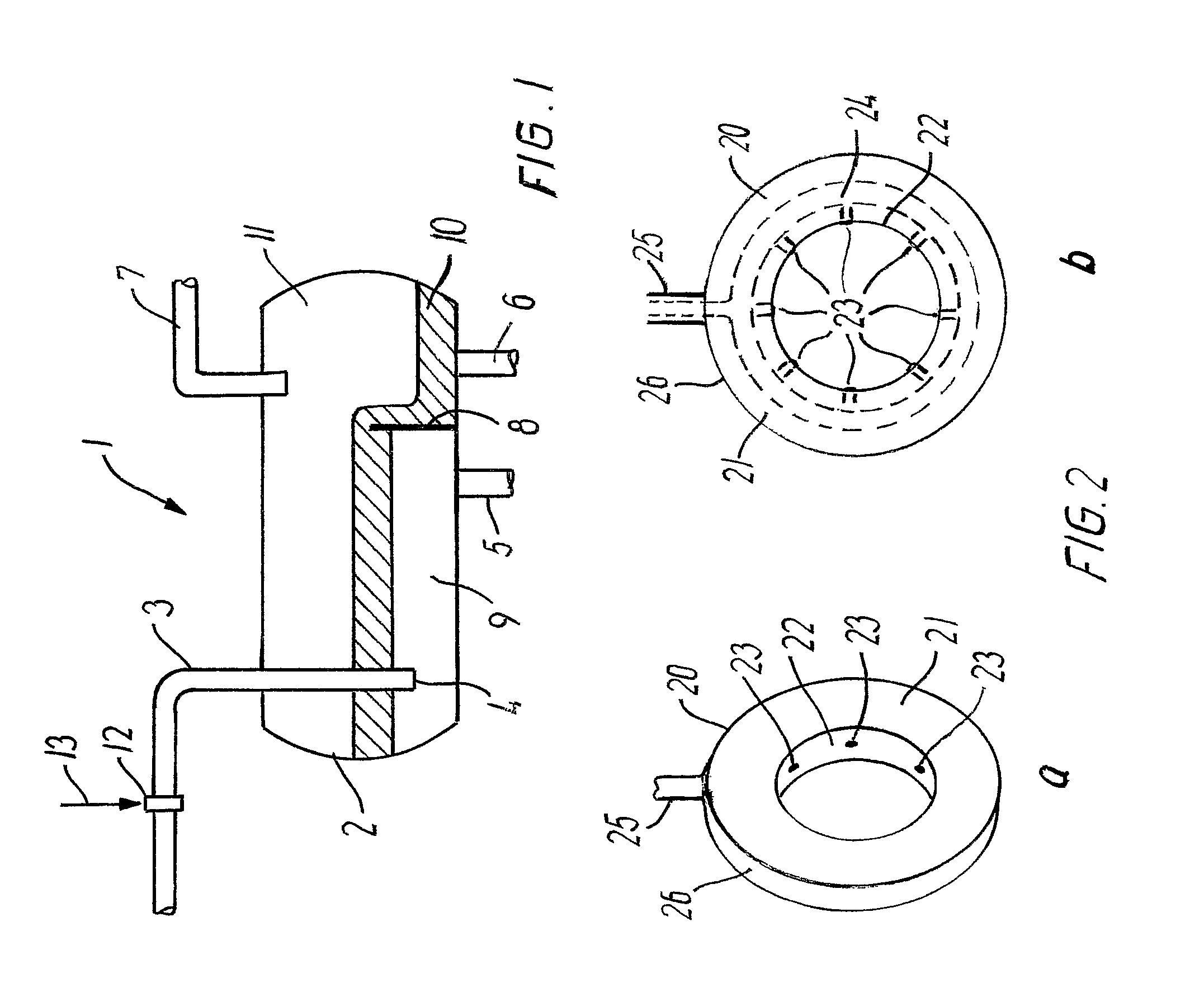
[0027]Reference is made to FIG. 1 where a gravity separator 1 is shown with a vessel 2 with an inlet duct 3 having a vessel entrance 4 located within vessel 2. The inflow of fluid mixture through entrance 4 spread itself freely into the vessel where gravity acts on the constituents in the mixture. The vessel 2 is further equipped with an outlet for water 5, an outlet for oil 6, and an outlet for gas 7. Within vessel 2 a weir plate 8 is provided that serves to separate water phase 9 from oil phase 10. Gas phase 11...


PUM

PropertyMeasurementUnit
Lengthaaaaaaaaaa
Volumeaaaaaaaaaa
Gravityaaaaaaaaaa

Abstract

A gravity separator includes a vessel within which a mixture containing water, oil, and gas can separate under gravity to form vertically discrete oil and water layers and a gas phase. An inlet duct communicates with a vessel entrance for the mixture containing water, oil, and gas. The inlet duct of the gravity separator includes a gas injector that injects a gaseous medium in a volume in the range of from 0.01-1.9 Sm3 of the gaseous medium per 1 m3 of the mixture into the mixture containing water, oil, and gas.

Description

CROSS-REFERENCE TO RELATED APPLICATION[0001]This is a national stage of PCT / IB06 / 053978 filed Oct. 27, 2006 and published in English.BACKGROUND OF THE INVENTION[0002]1. Field of Invention[0003]The present invention relates to a gravity separator, primarily of the kind in which a mixture flowing from an oil well, containing water, oil, and gas is separated into discrete, vertically spaced water, oil, and gas layers in a separator vessel for subsequent extraction from the vessel by way of a water outlet, oil outlet, and gas outlet, respectively.[0004]2. Description of the Prior Art[0005]Gravity separators have been known for many decades and have been used within the oil industry in various embodiments of which some are quite complex, including a number of static mixers and cyclones. Examples of known types of gravity separators can be found in e.g. GB 1327991 and WO 99 / 25454. U.S. Pat. No. 5,080,802 discloses an air flotation separator having an eductor for drawing gas into the incom...

Claims


Application Information

Patent Timeline
IPC IPC(8): C02F1/24B01D17/035C02F1/40
CPCB01D17/00B01D19/0005B01D17/0205B01D17/0208B03D1/242B03D1/247B03D1/1412C02F1/24C02F1/40C02F1/52C02F2101/32
Inventor FOLKVANG, JORN
Owner SHCLUMBERGER NORGE AS
Why Eureka
Try Eureka